Optical fibre temperature sensing method and sensor based on SAGNAC interferometer

A technology of optical fiber temperature and sensing method, which is applied in the direction of thermometers, instruments, thermometers and other physical/chemical changes. The effect of interference ability

A technology of optical fiber temperature and sensing method, which is applied in the direction of thermometers, instruments, thermometers and other physical/chemical changes. The effect of interference ability

CN1553158AInactive Publication Date: 2004-12-08BEIHANG UNIV

Image

  • Optical fibre temperature sensing method and sensor based on SAGNAC interferometer
  • Optical fibre temperature sensing method and sensor based on SAGNAC interferometer
  • Optical fibre temperature sensing method and sensor based on SAGNAC interferometer

Examples


Embodiment Construction

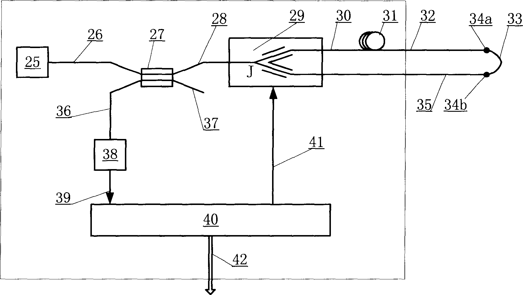
[0019] Such as image 3 As shown, the present invention consists of a wide-spectrum light source 25, a coupler 27, a Y waveguide modulator 29, a polarization-maintaining fiber delay loop 31, a polarization-maintaining fiber sensor head 33, a detector 38 and a signal detection circuit 40 to form a SAGNAC interferometer-based Fiber optic temperature sensor. The wide-spectrum light source is composed of a superluminescent diode SLD, or a light-emitting diode ELED, or a broadband erbium-doped light source SFS and its driving circuit. All devices in the optical path are connected by polarization-maintaining optical fibers, and the length of the polarization-maintaining optical fiber sensing head 33 is less than the coherence length of the interferometer. In the embodiment of the present invention, the fiber length of the polarization-maintaining optical fiber sensing head is less than 50mm, and it is connected to the polarization-maintaining optical fiber delay loop 31 and the Y-wa...


PUM


Abstract

In the present invention, a small section of polarization preserving fiber transducing head is added into closed light path of total polarization SAGNAC interferometer applying Y waveguide modulator and wide spectrum light source to create condition for generating polarization nonreciprocal after certain process is applied, generated polarization nonreciprocal phase-shift and temperature acted on transducing head is presented in linear ratio relationship when light path is in operation so phase shift can be measured accurately by utilizing circuit the same as used in close ring optical fibre gyro detection and furthermore temperature measurement is realized.

Description

technical field [0001] The invention relates to an optical fiber temperature sensing method based on a SAGNAC interferometer and a sensor thereof. Background technique [0002] SAGNAC interferometer is a typical interferometer, which is the basic structure of all optical gyroscopes. When the optical path is formed with optical fiber and equipped with a special detection circuit, it becomes a fiber optic gyroscope. For the principle and technology of fiber optic gyroscope, please refer to Herve C. Lefever's monograph "The Fiber-Optic Gyroscope" or its translation: Zhang Guicai, Wang Wei, "Fiber Optic Gyroscope", the following related discussions will be based on this. figure 1 It is a typical SAGNAC interferometer. The broadband light emitted by the broadband light source 1 passes through the optical fiber 2 to the coupler 3 and then enters the Y waveguide modulator 5 through the optical fiber 4. After passing through the Y waveguide modulator 5, the light is divided into two...

Claims


Application Information

Patent Timeline
08 Dec 2004
Publication
CN1553158A
IPC
G01J5/28; G01J5/58; G01J9/02; G01K11/32
Inventors
杨远洪