
Rapid length-measuring cutting process and apparatus for thin wall cylinder

A technology of thin-walled cylinders and cutting devices, which is applied in the direction of shearing devices, pipe cutting devices, manufacturing tools, etc., can solve the problems of large incision damage surface, many process steps, material waste, etc., and achieve excellent performance, accurate size, and economical The effect of raw materials

Active Publication Date: 2004-12-29
SHENZHEN XINTIAN TECH
View PDF0 Cites 16 Cited by
  • Summary
  • Abstract
  • Description
  • Claims
  • Application Information

AI Technical Summary

Problems solved by technology

[0002] The fixed-length cutting of thin-walled cylinders is widely used in industrial production. Taking the cutting of the flashlight body as an example, the existing cutting process adopts the cutting method of punching and shearing with a die on a punching machine, which relies on manual operation. Single punching and shearing, so not only the speed is slow, the number of process steps is large, but also the incision damage area is large, and the waste of materials is serious. Some manufacturers only waste raw materials every year. Millions of dollars

Method used


Image

  • Rapid length-measuring cutting process and apparatus for thin wall cylinder
  • Rapid length-measuring cutting process and apparatus for thin wall cylinder

Examples


Embodiment 1

[0020] Thin-walled cylinder quick cut-to-length process of the present invention, it comprises the steps:

[0021] 1) The cylinder feed assembly drives the cutting cylinder 3 to the cutting position;

[0022] 2) The cylinder rotating assembly drives the cutting cylinder 3 to rotate;

[0023] 3) The blade rotation assembly drives the cutting blade 4 to cut the cutting cylinder 3 .

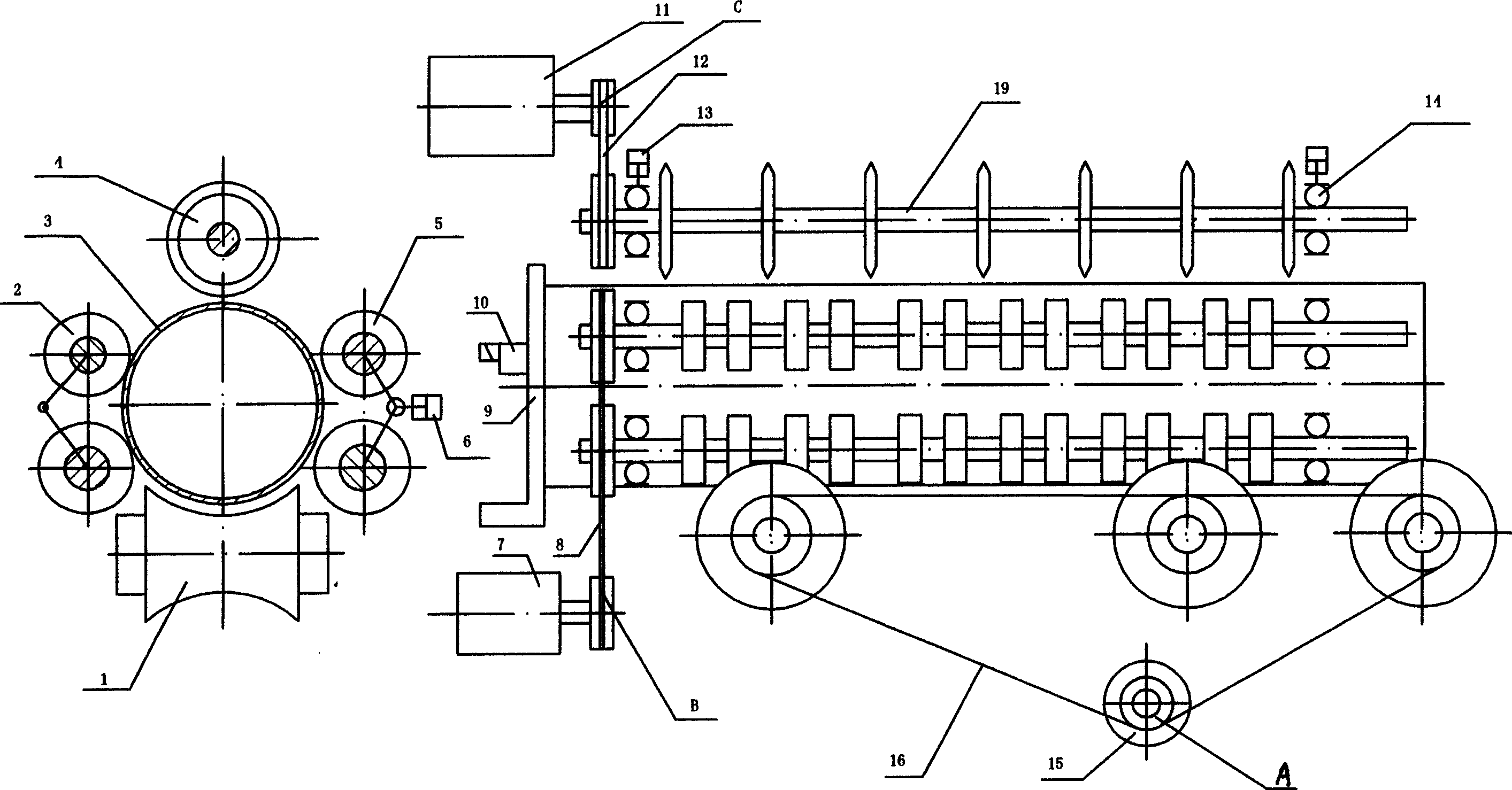
[0024] The thin-walled cylinder fast fixed-length cutting device used in the cutting process of the present invention has a structural schematic diagram as figure 1 As shown, the cylinder feed assembly includes a cylinder feed drive mechanism A and a feed wheel 1, the cylinder rotation assembly includes a cylinder rotation drive mechanism B and a cylinder rotation driving wheel 2, and the blade rotation assembly includes a blade Rotary drive mechanism C and several cutting blades 4, blade rotating shaft 19, wherein the output of cylinder feeding drive mechanism A is connected with the rotating sha...

Embodiment 2

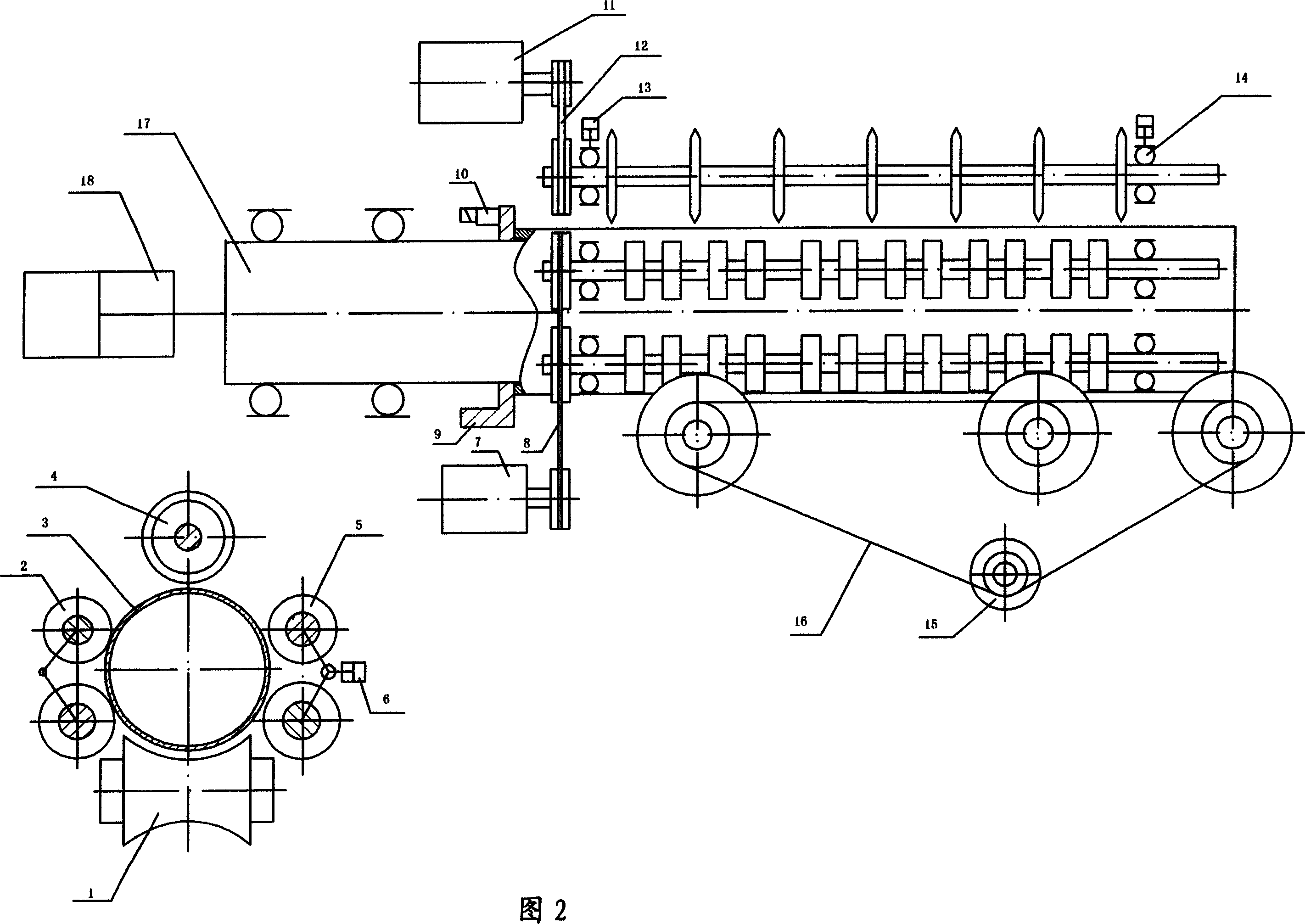
[0033] The thin-walled cylinder fast fixed-length cutting process of the present invention is the same as embodiment 1, and the thin-walled cylinder fast fixed-length cutting device of the present invention is as shown in Figure 2, and it is the structure that has mandrel rolling cutting, and the non-mandrel of embodiment 1 The difference of the rolling cutting structure is that a mandrel 17 driven by a control mechanism 18 is provided in the hollow cavity of the cutting cylinder 3, and the end of the mandrel 17 is supported on the frame. In this embodiment, the control mechanism 18 is an air cylinder.

[0034] The difference between this embodiment and Embodiment 1 in the cutting process is that when the cylinder to be cut is fed into the device, the mandrel 17 is stretched out under the action of the telescopic cylinder 18 to support the inside of the cylinder for rolling cutting. After the cylinder is cut off, the mandrel 17 is retracted under the action of the telescopic c...


PUM


Abstract

The present invention is fast fixed length thin-wall cylinder cutting process and apparatus. The cutting process includes the following steps: for the feeding assembly to deliver the cylinder to cutting position; for the rotating assembly to rotate the cylinder; for the cutter rotating assembly to drive the cutter to cut. The feeding assembly includes cylinder feeding mechanism and feeding wheel with rotating shaft connected to the output of the cylinder feeding mechanism; the rotating assembly includes rotating mechanism and rotating wheel with rotating shaft connected to the output of the rotating mechanism; and the cutter rotating assembly includes cutter driving mechanism, several cutters and cutter rotating shaft connected to the output of the cutter driving mechanism. The present invention has fast cutting sped, less cutting steps, accurate size and other advantages.

Description

1. Technical field: [0001] The invention relates to a cut-to-length process and device, in particular to a cut-to-length process and device for a thin-walled cylinder, and belongs to the innovative technology of the cut-to-length process and device for a thin-walled cylinder. 2. Background technology: [0002] The fixed-length cutting of thin-walled cylinders is widely used in industrial production. Taking the cutting of the flashlight body as an example, the existing cutting process adopts the cutting method of punching and shearing with a die on a punching machine, which relies on manual operation. Single punching and shearing, so not only the speed is slow, the number of process steps is large, but also the incision damage area is large, and the waste of materials is serious. Some manufacturers only waste millions of yuan in raw materials every year. 3. Contents of the invention: [0003] The purpose of the present invention is to provide a thin-walled cylinder rapid cu...

Claims


Application Information

Patent Timeline
Patent Type & Authority Applications(China)
IPC IPC(8): B23D21/04B26D1/15B26D3/16B26D7/27
Inventor 阳林黎勉孙友松章争荣潘晓涛
Owner SHENZHEN XINTIAN TECH
Learn More