Voltage transformer arrangement

A transformer and winding technology, which is applied in the direction of transformers, fixed transformers, transformer/inductor cores, etc., can solve the problems of limited application of transformers, save labor and manufacturing costs, simplify manufacturing procedures, and improve electrical safety. Effect

Active Publication Date: 2004-12-29
DELTA ELECTRONICS INC
View PDF0 Cites 8 Cited by
  • Summary
  • Abstract
  • Description
  • Claims
  • Application Information

AI Technical Summary

Problems solved by technology

Moreover, the melting point of the adhesive tape 24 is low, so the operating temperature limit of the entire transformer is limited by the melting point of the adhesive tape 24, causing the application of the transformer to be limited.

Method used


Image

  • Voltage transformer arrangement
  • Voltage transformer arrangement
  • Voltage transformer arrangement

Examples


Embodiment Construction

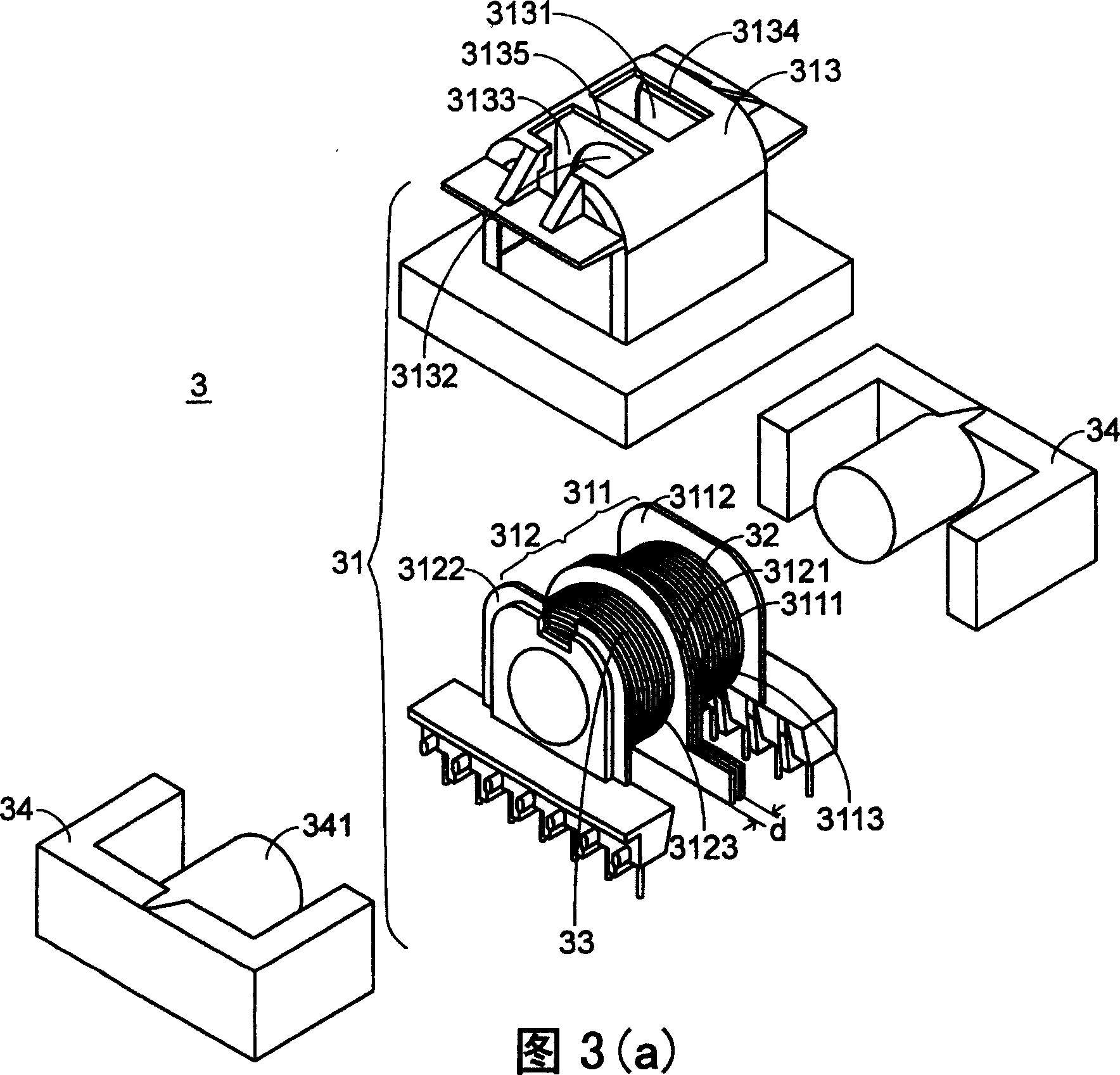
[0052] Please refer to FIG. 3( a ), which is a structural schematic diagram of a preferred embodiment of a transformer with leakage inductance in the present invention. As shown in FIG. 3( a ), the transformer 3 of the present invention includes a bobbin module 31 , a primary winding 32 , a secondary winding 33 and a core set 34 . Wherein, the winding frame module 31 has a first winding part 311 , a second winding part 312 and a winding frame cover 313 . The primary winding 32 and the secondary winding 33 are respectively wound on the first winding part 311 and the second winding part 312 . The iron core group 34 is EE type iron core (EE-core), EI type iron core (EI-core) or ER type iron core (ER-core). 34 generates electromagnetic coupling induction with the primary winding 32 and the secondary winding 33 to achieve the purpose of voltage conversion.

[0053] Please refer to Fig. 3 (a), the first winding part 311 and the second winding part 312 of the winding frame module 3...


PUM


Abstract

The invention relates to a transformer arrangement which comprises a primary coiling, a secondary coiling, a coiling bracket module and an iron core set, wherein the iron core set is arranged in the coiling bracket module, the coiling bracket module includes a first coiling element and a second coiling element, the first coiling element is used for coiling the primary coiling, the second coiling element is used for coiling the secondary coiling, the first coiling element and the second coiling element each has a first lateral plate, and the first coiling element and the second coiling element are spaced or connected through the first lateral plate, thus separating the primary coiling and the secondary coiling so as to increase leakage inductance and electric safe distance.

Description

technical field [0001] The present invention relates to a transformer structure, especially a transformer structure that can increase leakage inductance, improve electrical safety, has a simple structure, and can save assembly time, assembly labor and manufacturing cost. Background technique [0002] Transformers are electronic components that are often used in various electrical equipment. see figure 1 , which is a schematic structural diagram of a traditional transformer. Such as figure 1 As shown, the transformer 1 mainly includes a magnetic core assembly 11 , a bobbin base 12 , a primary winding coil 13 , and a secondary winding coil 14 . Wherein, the primary winding 13 and the secondary winding 14 are stacked up and down in the winding area of ​​the winding base 12 and are insulated and separated from each other by an adhesive tape 15 (tape). The core group 11 is usually an EE-type core (EE-core), an EI-type core (EI-core) or an ER-type core (ER-core), which can set...

Claims


Application Information

Patent Timeline
Patent Type & Authority Applications(China)
IPC IPC(8): H01F27/24H01F27/28H01F30/06
Inventor 张世贤
Owner DELTA ELECTRONICS INC
Why Eureka
Try Eureka