Automatic detection meethod and system for smooth surface flaw

An automatic detection and smooth surface technology, applied in measuring devices, material analysis through optical means, instruments, etc., can solve the problems of too small detection caliber, defects cannot be accurately calibrated, and low efficiency, so as to improve work efficiency, The effect of efficient objective detection and digital evaluation

Active Publication Date: 2005-01-12
ZHEJIANG UNIV
View PDF0 Cites 58 Cited by
  • Summary
  • Abstract
  • Description
  • Claims
  • Application Information

AI Technical Summary

Problems solved by technology

These methods can be used for reference, but the digital evaluation system for large-caliber surface defects has many shortcomings: the uncertainty and low efficiency of visual observation; the light source and system of the detection device are not unified with international standards; Detection caliber; defects cannot be accurately calibrated, etc.

Method used


Image

  • Automatic detection meethod and system for smooth surface flaw
  • Automatic detection meethod and system for smooth surface flaw
  • Automatic detection meethod and system for smooth surface flaw

Examples


Embodiment 1

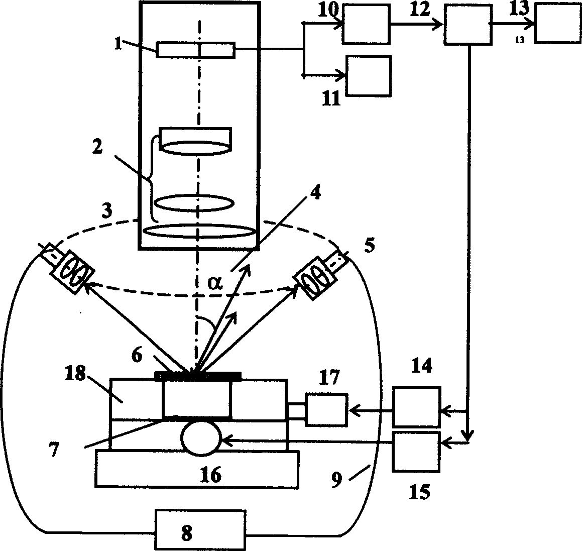
[0060] The automatic detection method and system of the smooth surface defect of the present invention are as attached figure 1 As shown, when the diameter of the tested surface is small, the tested component 6 is placed on the workbench 18, and the dark background 7 is under the tested component. The adjustable frame 3 enables the fiber optic light source (the light source is an incandescent lamp and can be adjusted in light intensity) 9 to irradiate the tested component at a specific angle, and the incident light is reflected by the surface on the object surface of the optical system and emerges from the other end, while the surface Part of the scattered light induced by the edge of the defect is reflected at an angle of α and then collected by the zoom optical micro-magnification system 2 and imaged on the CCD1. One path of the image passes through the monitor 11 for monitoring during detection, and the other path passes through the image acquisition system 10 to send the c...

Embodiment 2

[0062] When the diameter of the surface to be tested is large, the automatic detection system for smooth surface defects is shown in Figure 1, and the placement and adjustment of the tested components are as in Example 1. When the surface to be measured is a large diameter, it can be carried out as attached Figure 4 In the scanning mode shown, the computer 12 controls the driving circuits 14, 15 of the X and Y worktables of the sub-aperture scanning, so that the X and Y motors 16 and 17 drive the worktable 18 to perform multiple sub-aperture scans in the X and Y directions. Obtain full aperture defect image data. And the sub-aperture mosaic is completed according to the coordinates of each scanning aperture. Large-aperture detection must be composed of multiple sub-apertures, so the amount of data is very large. In order to compress the amount of data, the sub-apertures with no defect information can be removed, and at the same time, the requirements between the accuracy of ...


PUM

PropertyMeasurementUnit
widthaaaaaaaaaa
lengthaaaaaaaaaa

Abstract

Based on standard of faulty work and light scattering characteristic of faulty work, new type computer aided digitized testing device suitable to large caliber, sub aperture scattering imaging is built. Features of the testing device are as following: Kohler cold light source arranged in multiple optical fiber and multiple azimuth angles; reflecting imaging of scattered light from faulty work on surface to be tested; scattered light collected by micro zooming system and imaged on CCD; Movable operating table in X, Y directions controlled by computer through multiple sub apertures scans surface to be tested in large caliber; building up mathematical model pattern recognition based on mathematical morphology, and software for calibrating size of faulty work. The invention builds objective digital evaluation system, raises working efficiency. The device is suitable for recognizing and evaluating faulty work in size larger than several micros.

Description

technical field [0001] The invention relates to an automatic detection method and system for smooth surface defects. Background technique [0002] In optical engineering, large-scale integrated circuit manufacturing, precision machinery and other related industries and national defense high-tech fields, there are strict requirements on the surface defects of some high-precision optics, metals and other materials, especially for some used in optical systems. The defects on the surface of high-precision optical components are more strictly controlled. The defect detection on the smooth surface of optical components must be carried out according to the defect engineering standards at home and abroad, because the scattering of defects will greatly consume light energy and reduce the optical components. Laser damage threshold, causing new damage to optical components, destroying the film layer, seriously affecting the normal operation of the optical syst...

Claims


Application Information

Patent Timeline
Patent Type & Authority Applications(China)
IPC IPC(8): G01N21/956
Inventor 杨甬英卓永模
Owner ZHEJIANG UNIV
Why Eureka
Try Eureka