
Parallel optical array assembly with standard MPO interface

An optical fiber array, a standard technology, applied in the field of parallel optical fiber array components, can solve the problem that the positioning accuracy of optical fibers is not very high

Inactive Publication Date: 2005-01-12
武汉海博光技术有限公司
View PDF0 Cites 7 Cited by
  • Summary
  • Abstract
  • Description
  • Claims
  • Application Information

AI Technical Summary

Problems solved by technology

The 1×N standard MPO interface has good consistency, but the positioning accuracy of each fiber with a 45° bare fiber head at the other end is not very high

Method used


Image

  • Parallel optical array assembly with standard MPO interface
  • Parallel optical array assembly with standard MPO interface
  • Parallel optical array assembly with standard MPO interface

Examples


Embodiment Construction

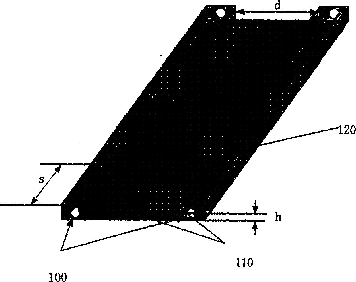
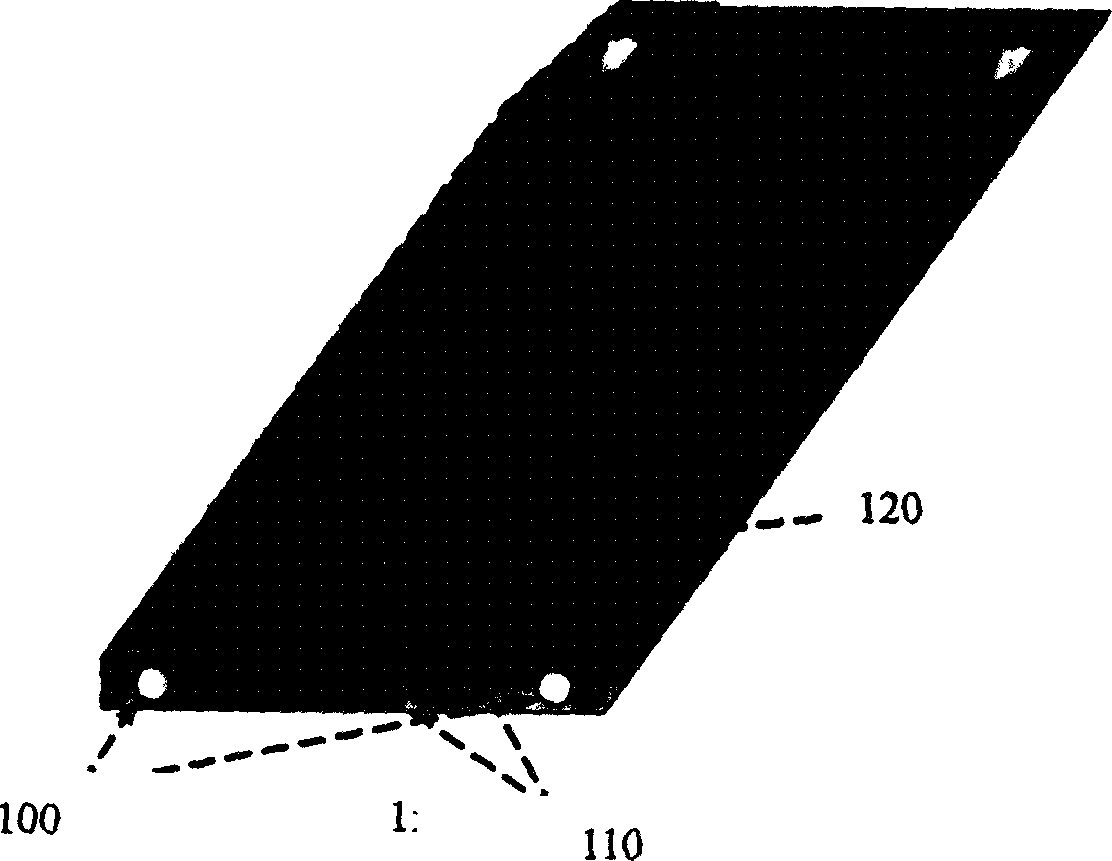
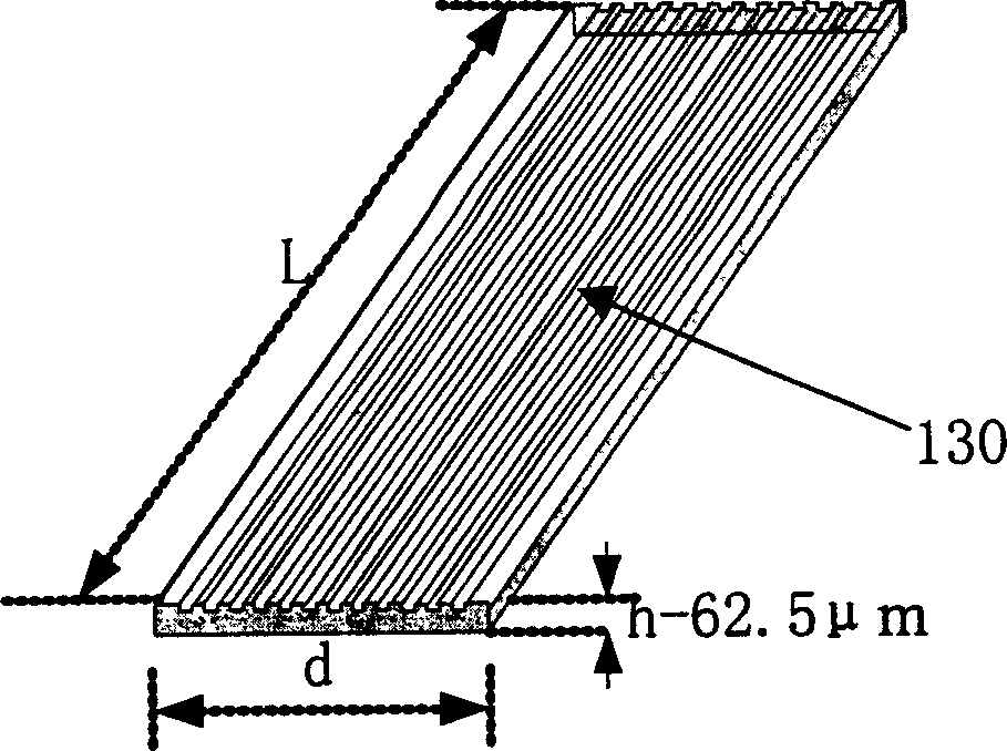
[0015] First, using traditional standard compression molding techniques to make such as figure 1 The traditional 1×N standard MPO socket component shown in the figure has the following three key functions: First, there are two positioning pin holes 100 that penetrate the entire device on both sides, which are used when two opposite devices are docked. , so that all optical channels in the two devices are fully coupled; second, there is a 1×N core fiber positioning hole 110 at one end, which is used for the strict positioning of 1×N optical fibers; third, after the 1×N positioning hole , there is a 1×N core optical fiber positioning V-shaped groove 120, its height and horizontal position are strictly the same as the previous optical fiber positioning holes, when it is used to discharge optical fibers, guide each optical fiber into each positioning hole, and at the same time, for each Fiber optics play a supporting role. The traditional standard 1×N MPO socket component can als...


PUM


Abstract

The subassembly includes standard MPO connector, groove substrate, and top cover substrate and optical fiber. One end of the subassembly is traditional standard 1XN MPO connector in order to keep compatibility, and the other end is coupled to VCSEL chip of face emission laser array and light receiving PIN chip. Grooves are etched on a substrate, and lines on two sides of grooves are utilized to posit each optical fiber so as to fabricate fiber array module. Both VCSEL chip and PIN chip is made through photo etching providing high positioning accuracy, which guarantees coupling efficiency. Positioning accuracy for each optical fiber is 0.2-0.5 micro.

Description

technical field [0001] The invention belongs to the field of optical communication, parallel processing high-performance computer optical interconnection technology and other fields, and especially relates to a parallel optical fiber with a standard MPO interface. Array components. Background technique [0002] In recent years, due to the rapid development of Internet communication network, mobile communication and multimedia services, IP data flow has increased rapidly, and the communication equipment and high-performance computer systems required by optical communication networks are developing towards the T-bit level. Driven by a strong market, a large number of new passive devices and active devices used in the information field have emerged. Surface-emitting laser array VCSEL chips, optical receiving PIN chips, planar waveguide chips for multiplexing, demultiplexing, and beam splitters for various purposes, and micro-opto-electromechanical switc...

Claims


Application Information

Patent Timeline
Patent Type & Authority Applications(China)
IPC IPC(8): G02B6/38
Inventor 陈绍仟陈鹰
Owner 武汉海博光技术有限公司
Learn More