

Information acquisition apparatus, cross section evaluating apparatus, cross section evaluating method
A technology of acquisition device and evaluation device, which is applied in the direction of circuits, discharge tubes, electrical components, etc., and can solve the problems of not being able to specify the cutting position and a large amount of work
- Summary
- Abstract
- Description
- Claims
- Application Information
AI Technical Summary
Problems solved by technology
Method used
Image

Examples
Embodiment approach 1
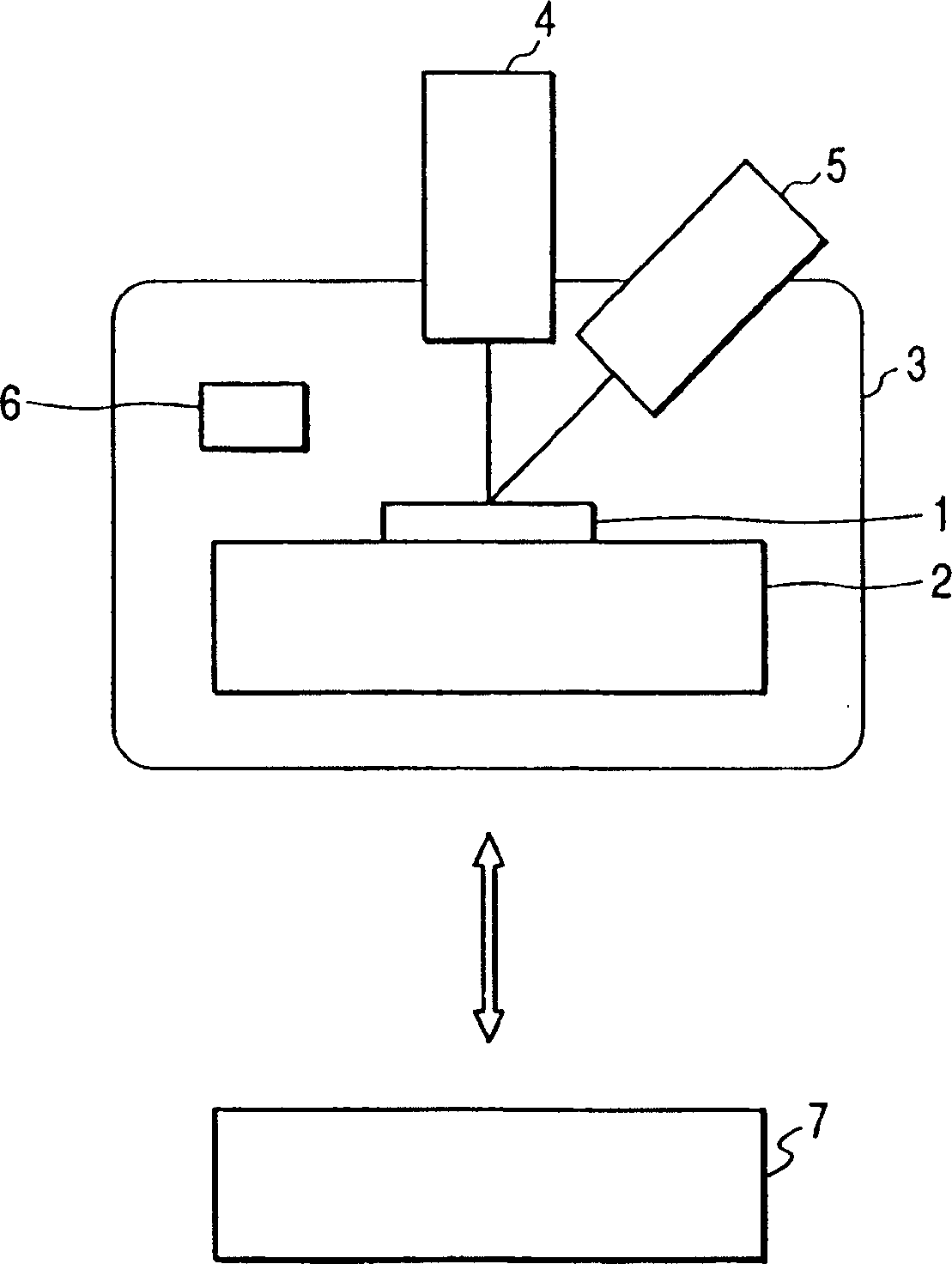
[0031] figure 1 The configuration of a scanning electron microscope used for cross-sectional observation is schematically shown, which constitutes the first embodiment of the cross-sectional evaluation device of the present invention. The electron microscope is provided with a temperature maintaining unit 2 on which a sample 1 is fixed and which maintains the temperature of the sample at a predetermined temperature. The temperature maintaining unit 2 can be accommodated in the sample chamber 3 .
[0032] The sample chamber 3 is provided with an ion beam generating unit 4 for irradiating the sample 1 fixed to the temperature maintaining unit 2 with an ion beam, and an electron beam generating unit 5 for irradiating the sample with an electron beam, and is also provided with an The electron detector 6 emits secondary electrons emitted from the sample 1 by beam irradiation. The inside of the sample chamber 3 can be evacuated by a pump not shown in the figure to maintain a prede...
Embodiment approach 2
[0072] Figure 4 The configuration of a scanning electron microscope used for cross-sectional observation is schematically shown, which constitutes a second embodiment of the cross-sectional evaluation device of the present invention. The configuration of this electron microscope is basically the same as that of the first embodiment, except that an X-ray detector 11 for detecting characteristic X-rays emitted from a sample 1 in response to electron beam irradiation is provided. exist Figure 4 In , components equivalent to those shown previously are denoted by like numerals.
[0073] The control unit 7 receives detection signals of the X-ray detector 11 , and by scanning the sample 1 with the electron beam of the electron beam generating unit 5 , elemental analysis can be performed within the scanning range. Therefore, this embodiment enables elemental analysis in addition to SEM observation and SIM observation.
[0074] The electron microscope of this embodiment, in additi...
Embodiment approach 3
[0084] In addition to the configurations of the previous Embodiments 1 and 2, it is possible to provide such as Image 6 The reactive gas shown in is introduced into conduit 13, thereby introducing the reactive gas into the vicinity of the sample during FIB processing. Valve 14 and gas source container 15 are also shown.
[0085] In this case, depending on the selected ion beam, gas and temperature conditions, ion beam assisted gas etching or gas deposition can be performed to process the sample surface into arbitrary shapes. Observation of the surface thus processed (SEM observation or SIM observation) makes it possible to obtain accurate information on the surface thus processed into a desired shape.
[0086] The gas introduction holes are placed three-dimensionally so as not to interfere with the detector or the beam system.
[0087] A well-known example of FIB-assisted deposition is the use of tungsten hexacarbonyl (W(CO) 6 ) and tungsten deposition of Ga-FIB.
[0088]...
PUM
 Abstract
Description
Claims
Application Information