Construction optical visual sense transducer calibration method based on plane targets

A technology of visual sensor and calibration method, which is applied in the field of measurement, can solve problems such as difficult maintenance, difficult implementation, and difficulty in obtaining high-quality calibration images, and achieve the effects of improving calibration accuracy, reducing labor intensity, and simplifying the calibration process

Inactive Publication Date: 2005-01-19
BEIHANG UNIV
View PDF0 Cites 50 Cited by
  • Summary
  • Abstract
  • Description
  • Claims
  • Application Information

AI Technical Summary

Problems solved by technology

This method has the following disadvantages: First, the extraction accuracy of the image point is low due to the reflection of the teeth
Second, external equipment is required to strictly adjust the optical plane to be perpendicular to a certain reference plane (toothed target base plane), which is difficult to achieve and is not suitable for on-site calibration
This met

Method used


Image

  • Construction optical visual sense transducer calibration method based on plane targets
  • Construction optical visual sense transducer calibration method based on plane targets
  • Construction optical visual sense transducer calibration method based on plane targets

Examples


Embodiment

[0081] The actual design of the laser vision sensor is as follows: Figure 5 shown. Figure 5 It is the physical picture of the laser vision sensor installed on site. Figure 5 Among them, 6 is the sensor power line and output signal interface terminal, 7 is the CCD camera window, 8 is the sensor installation mechanism, 9 is the sensor housing, and 10 is the laser projector window.

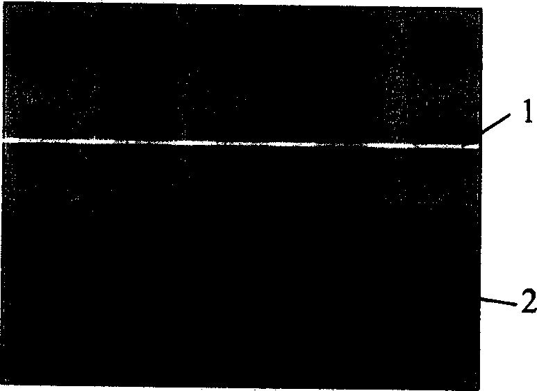
[0082] Following the steps described above, use the figure 1 The planar calibration target shown calibrates the CCD camera and the structured light vision sensor. Targets at two positions are used to calibrate the structural parameters of the sensor, and the part of the calibration image such as Image 6 , 7 as shown, Figure 8 is the global world coordinates of the marked feature points on the obtained light plane, Figure 9 is the normalized image coordinates of the marked feature points on the light plane. The obtained calibration parameters are:

[0083] Camera internal parameters: ...


PUM


Abstract

This invention belongs to measuring technique field and relates to an improvement for the sensor parameters calibration in the measuring of optical three-dimensional vision. The steps of the invention are the following: to set target, to photo target image; to calibrate inner parameters in camera; to photo sensor calibration image; to distortion correct the sensor calibration image; to calculate sensor calibration characteristic points; to calculate the local world coordinates of sensor calibration characteristic points; calculate conversion matrix of camera; to calculate whole world coordinates of calibration characteristic points; to calibrate structure parameters of laser vision sensor; to save the parameters. This method is of high calibration accuracy and simple process and needn't accessory equipment with high cost and is especially suitable to the on-spot calibration of optical vision sensor.

Description

technical field [0001] The invention belongs to the technical field of measurement and relates to the improvement of a sensor parameter calibration method in structured light three-dimensional vision detection. Background technique [0002] Accurately obtaining 3D information of the objective world is a key issue in many fields such as rapid product design, product quality control, CAD / CAM, medical diagnosis, cultural relic identification, clothing design, automatic navigation, and virtual reality systems. As one of the main means of obtaining 3D information, the structured light visual inspection method has the advantages of large range, non-contact, fast speed, good system flexibility, and moderate accuracy. It is widely used in 3D model reconstruction, 3D information measurement of object surface contours and other fields. The effective calibration method of structured light vision sensor model parameters has always been an important research content. At present, there a...

Claims


Application Information

Patent Timeline
IPC IPC(8): G01D5/26G01D18/00
Inventor 周富强张广军
Owner BEIHANG UNIV
Why Eureka
Try Eureka