Jet Aerating Reactor

A technology of jet aeration and reactor, applied in the direction of water aeration, fluid mixer, chemical instrument and method, etc., can solve the problem of poor propulsion performance, poor mixing effect of water and gas, and insufficient oxygenation capacity in the boundary area of ​​jet flow Ideal and other issues, to achieve the effect of improving convection and diffusion capacity, small diameter, and enhanced turbulence

Inactive Publication Date: 2005-01-26
CHONGQING UNIV
View PDF1 Cites 34 Cited by
  • Summary
  • Abstract
  • Description
  • Claims
  • Application Information

AI Technical Summary

Problems solved by technology

[0002] The currently used jet aeration reactor has poor water and air mixing effect, unsatisfactory oxygenation capacity, poor propulsion performance and small service area in the jet boundary area

Method used


Image

  • Jet Aerating Reactor

Examples


Embodiment Construction

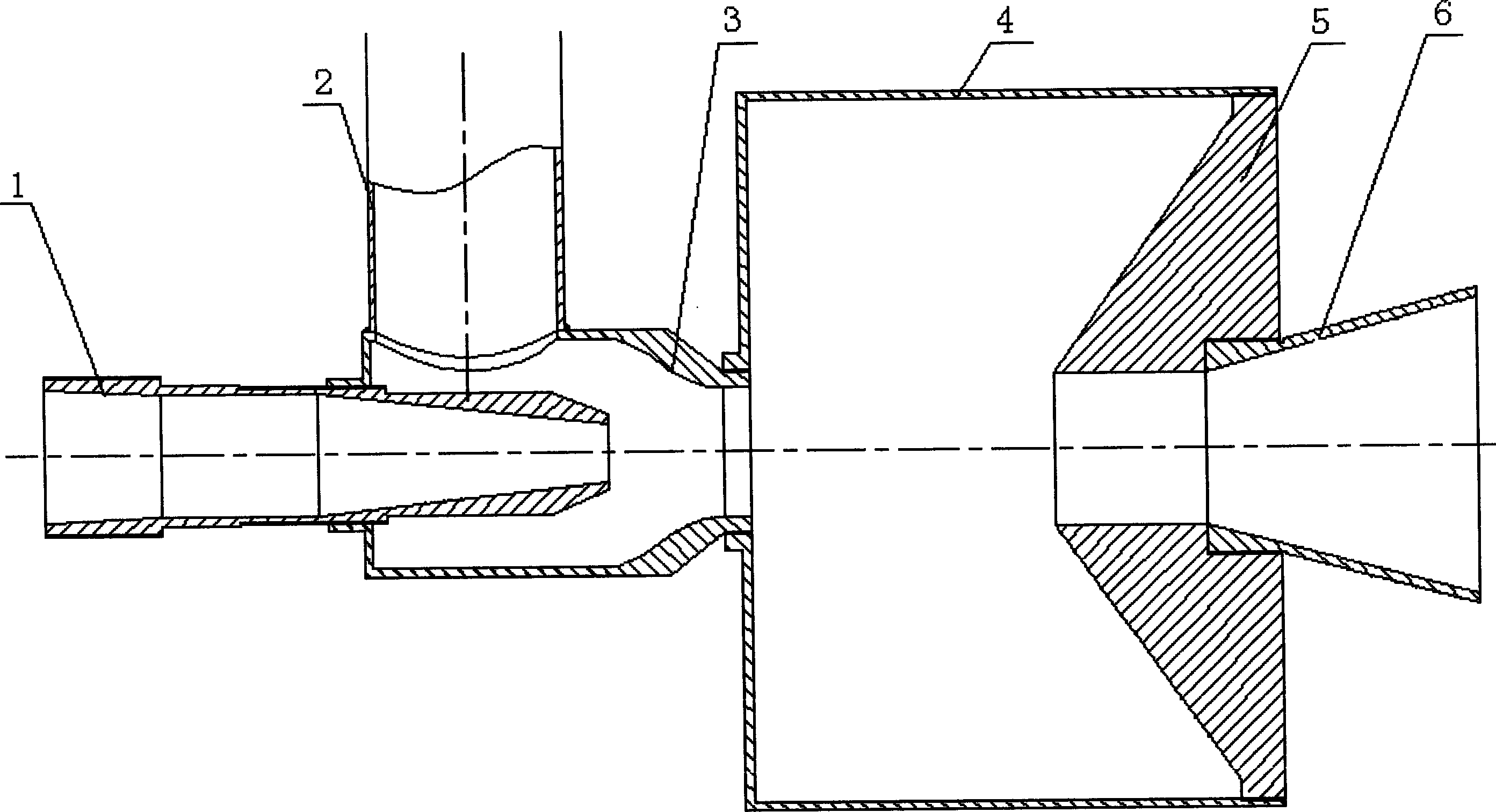
[0011] Nozzle 1, upper nozzle body 3, self-excited oscillating mixing chamber 4, lower nozzle body 5 and short pipe 6 are installed on the same center line in sequence, and the suction pipe 2 is vertically installed on the outer surface of the hollow cylindrical section of the upper nozzle body . The through hole in the nozzle 1 is composed of a cylindrical hole and a conical hole, and the cone angle of the conical hole is 12.5°-13.5°. The connection mode between the nozzle 1 and the upper nozzle body 3 is screw connection or welding or flange connection. The purpose of designing the inner contour curve of the suction chamber in the upper nozzle body is to improve the flow coefficient of the two-phase flow of water and gas entering the inlet hole of the self-excited oscillation mixing chamber. The inner contour curve is a straight line segment and an outwardly convex transition circle The arc and the inwardly concave high-degree equation curve are smoothly connected in turn. ...


PUM


Abstract

The invention discloses a jet aeration reactor for industrial or urban sewage treatment, which comprises a nozzle, a top nozzle member, a self-induced vibration mixing chamber, a lower nozzle member and short tube, wherein the air intake duct is arranged on the top nozzle member and is in communication with the induction chamber in the top nozzle member, the nozzle through-hole, the induction chamber in the top nozzle member, the self-oscillation mixing chamber, the lower nozzle member and the short tube are in communication.

Description

Technical field: [0001] The invention relates to an industrial wastewater or urban domestic sewage treatment device. The device is widely used in printing and dyeing, textile, slaughtering, leather, paper, sugar, pharmaceutical, brewing, beer, food processing and other industries, and can also be used in groundwater iron removal, fish ponds and live fish transportation oxygenation and other industries. Background technique: [0002] The currently used jet aeration reactor has poor water and gas mixing effect, unsatisfactory oxygenation capacity, poor propulsion performance and small service area in the jet boundary area. The utility model patent number is 89201391.5, and its invention name is "oscillating pulse jet nozzle for roller cone bit". The nozzle consists of upper and lower nozzle bodies. Composition, the shape of the upper nozzle body is a stepped cylinder, the nozzle body flow channel in the body is composed of two exponential curved surfaces and three cylindrical...

Claims


Application Information

Patent Timeline
Patent Type & Authority Applications(China)
IPC IPC(8): B01F3/04B01F5/02C02F7/00
CPCY02W10/10
Inventor 廖振方
Owner CHONGQING UNIV
Why Eureka
Try Eureka