Combined extrusion method using transition cellpacking to realize helical slow-wave structure

A technology of slow wave structure and transition tube, which is applied in the direction of circuit components of transit time electronic tubes, discharge tube/lamp manufacturing, electrical components, etc. complex structure, etc.

Inactive Publication Date: 2005-01-26
INST OF ELECTRONICS CHINESE ACAD OF SCI
View PDF0 Cites 10 Cited by
  • Summary
  • Abstract
  • Description
  • Claims
  • Application Information

AI Technical Summary

Problems solved by technology

The structure of this kind of composite shell is more complex, the processing is more difficult, and the processing of the hot extrusion die is also very difficult
The hot extrusion process of this shell is also competent for the helical slow wave structure below the X-band. For the helical slow-wave structure above the X-band, due to the complex shape of the composite shell, the mechanical strength is relatively high, and the elastic deformation and plastic deformation are relatively small, so the cold extrusion process cannot be used
As for the hot extrusion process of overall heating, it is not applicable due to the difficulty in removing the mold
In addition, due to the small thermal deformation, it is easy to break the medium clamping rod during the extrusion process, so there are some difficulties in the hot extrusion process using tube shell heating

Method used


Image

  • Combined extrusion method using transition cellpacking to realize helical slow-wave structure
  • Combined extrusion method using transition cellpacking to realize helical slow-wave structure
  • Combined extrusion method using transition cellpacking to realize helical slow-wave structure

Examples


Embodiment Construction

[0050] The following combines the principle Figure 6 The combined extrusion method of realizing the helical slow wave structure by utilizing the transition shell of the present invention is described.

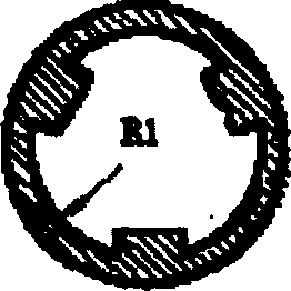
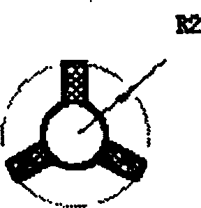
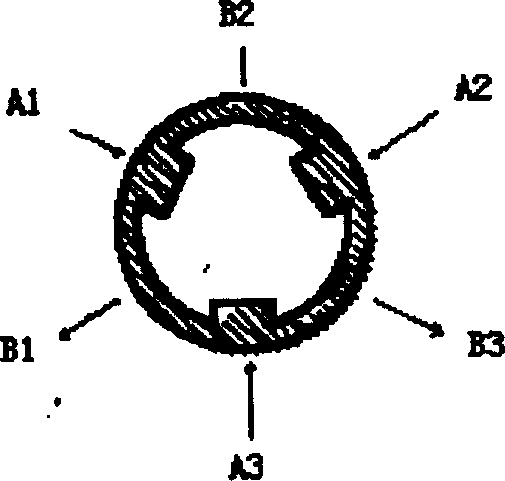
[0051] 1. The helical slow wave structure realized by the present invention is different from the original helical slow wave structure. The original helical slow wave structure is composed of shell 1, helix 2 and media 31, 32 and 33, such as figure 1 , figure 2 , image 3 and Figure 4 shown. And the main feature of the present invention is to introduce the transition shell 5, Figure 61 is the real shell. After the transition shell 5 is introduced, the overall performance of the helical slow wave structure can surpass the original helical slow wave structure in some respects. For example, the transition shell 5 of the present invention can be made of oxygen-free copper and other materials with very good conductivity, while the original shell has to use other materials...


PUM


Abstract

The invention relates to a travelling wave tube manufacturing technique, especially a novel technique of manufacturing spiral slow-wave structure (SWS). It has the following steps: 1. fixing spiral line together with medium rod by mould; 2. axially sending them in a transition tube casing; 3. squeezing the transition tube casing together with them by the technical method of elastic or plastic deformation cold extrusion so as to obtain a transition module of the SWS; 4. firstly heating the tube casing to 800-1000 deg.C, axially sending the transition module at room temperature in the tube casing at high temperature, and locating; 5. cooling the whole workpiece obtained in the step 4 to room temperature, enclasping the transition module with the tube casing by the shrinkage of the tube casing, thus obtaining the SWS product. It is especially applied to composite tube casing with a more complex structure.

Description

technical field [0001] The invention relates to the manufacturing technology of the traveling wave tube, in particular to a novel process for manufacturing the helical slow wave structure. Background technique [0002] The helical slow wave structure is the core component of the traveling wave tube. Because the helical slow-wave structure has broadband characteristics, the traveling wave tube can generate and amplify microwave or millimeter waves in a wide frequency band. Therefore, traveling wave tubes have important applications in electronic countermeasures, especially in electronic interference. However, the manufacture of the helical slow wave structure is a very complicated process, and its process methods are divided into cold extrusion and hot extrusion. Among them, cold extrusion is divided into two types: elastic deformation extrusion and plastic deformation extrusion, while hot extrusion can be divided into two types: overall heating extrusion and shell heating ...

Claims


Application Information

Patent Timeline
IPC IPC(8): H01J9/00H01J23/26
Inventor 王莉刘胜英
Owner INST OF ELECTRONICS CHINESE ACAD OF SCI
Why Eureka
Try Eureka