Power amplifier module

A technology for power amplifiers and single-ended amplifiers, applied in amplifiers, amplifier combinations, differential amplifiers, etc., can solve the problems of unsuitable for asymmetrical input, insufficient stability, inaccurate quiescent current control, etc., to achieve accurate quiescent current control, The effect of quiescent current control enhancement

Inactive Publication Date: 2005-02-02
NXP BV
View PDF4 Cites 8 Cited by
  • Summary
  • Abstract
  • Description
  • Claims
  • Application Information

AI Technical Summary

Problems solved by technology

This prior art amplifier has some important drawbacks: quiescent current control is imprecise and not stable enough
A drawback of this amplifier circuit is that the structure cannot be used for asymmetrical input

Method used


Image

  • Power amplifier module
  • Power amplifier module
  • Power amplifier module

Examples


Embodiment Construction

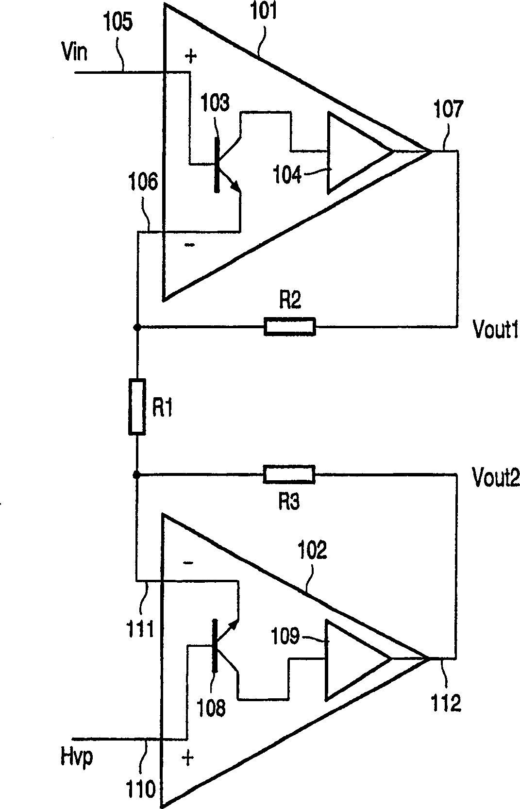
[0023] figure 2 A circuit diagram of a power amplifier module according to the invention is shown. The power amplifier module includes a single-ended amplifier 101 and a single-ended amplifier 102 . In general, a single-ended amplifier is an amplifier that has a single output terminal that operates with respect to ground. The voltage difference between the input terminal and ground is amplified.

[0024] The single-ended amplifier 101 includes an npn transistor 103 and an end block 104 . The bias terminal of the transistor 103 is connected to the non-inverting terminal 105 of the single-ended amplifier 101 , and the emitter of the transistor 103 is connected to the inverting terminal 106 of the single-ended amplifier 101 . The collector of transistor 103 is connected to the input of end block 104 . The output of the end block 104 is connected to the output 107 of the single-ended amplifier 101 .

[0025] The single-ended amplifier 102 has a corresponding npn transistor 1...


PUM


Abstract

The invention relates to a power amplifier module comprising single-ended amplifiers (101 and 102) which are arranged in a BTL configuration. The single-ended amplifiers (101 and 102) have low-impedance inverting inputs coupled by a resistor R1 for improved stability and quiescent current control.

Description

technical field [0001] The present invention relates to a power amplifier module, in particular to an audio power amplifier. Background technique [0002] The prior art shows many power amplifiers that can be used for audio amplification. Specifically, US Patent No. 5,216,381 shows a unity-gain final stage, especially for a monolithically-integrable power amplifier using an AB-driver type N-channel MOS transistor as a power supply device. The power amplifier includes a high-gain feedback differential amplifier, the inverting input of which is connected to the input of the power amplifier. This prior art amplifier has some important drawbacks: inaccurate quiescent current control and insufficient stability. [0003] figure 1 A corresponding unity-gain final stage comprising a pair of terminal N-channel MOS power transistors 1 and 2 is shown. The first transistor 1 has its drain connection connected to a supply voltage 3 and its source connection is connected to the drain ...

Claims


Application Information

Patent Timeline
Patent Type & Authority Applications(China)
IPC IPC(8): H03F3/68H03F3/18H03F3/30H03F3/45
CPCH03F3/45475H03F3/3033H03F3/30
Inventor M·G·J·维斯蒂根
Owner NXP BV
Why Eureka
Try Eureka