Silencing device of compressor

A technology of a muffler and a compressor, applied in the field of compressors, can solve the problems of small internal space of the muffler, poor noise reduction effect, poor noise reduction effect, etc., and achieve the effects of increasing the expansion ratio, improving the noise reduction effect, and increasing the noise reduction volume.

Inactive Publication Date: 2005-02-16
LG ELECTRONICS (TIANJIN) APPLIANCES CO LTD
View PDF0 Cites 6 Cited by
  • Summary
  • Abstract
  • Description
  • Claims
  • Application Information

AI Technical Summary

Problems solved by technology

Since the shape of the outer muffler 82 is the same as that of the inner muffler 81 and is a five-lobe structure, the inner space of the outer muffler 82 is small, and the muffler is performed by expanding the volume, and the muffler effect is not good, especially for special frequency bands. Noise, the noise reduction effect is worse
[0009] The structure of the existing muffler 80 is relatively simple, and the internal space of the muffler is small, and the noise reduction effect is not good by expanding the volume, especially for the noise of special frequency bands, the noise reduction effect is even worse

Method used


Image

  • Silencing device of compressor
  • Silencing device of compressor
  • Silencing device of compressor

Examples


Embodiment Construction

[0020] The muffler of the compressor of the present invention will be described with reference to the drawings and embodiments.

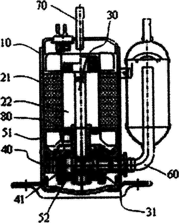
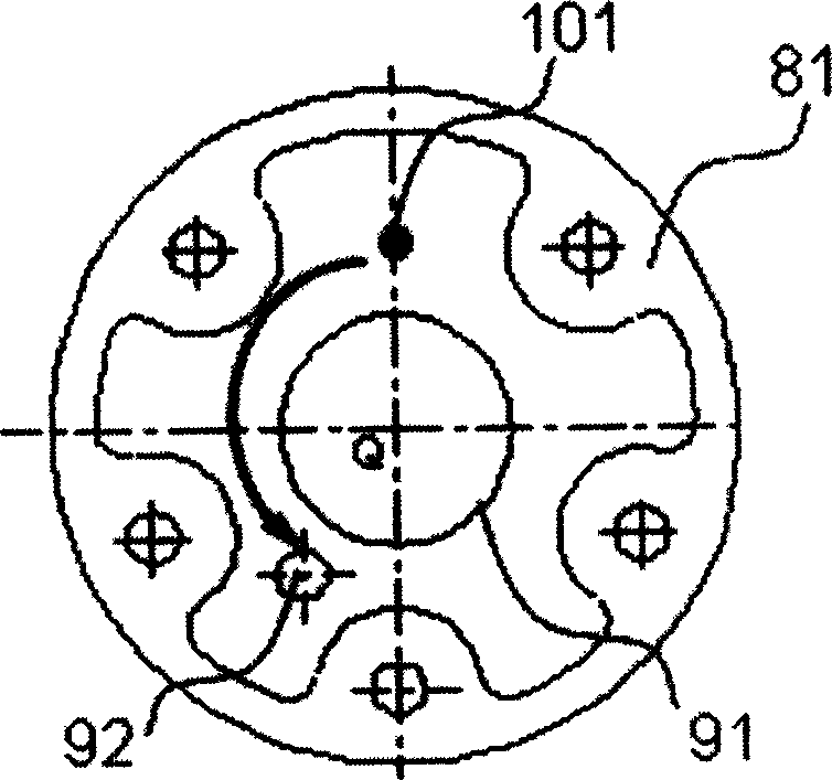
[0021] Such as Figure 4 , 5 As shown, the structure of the muffler of the compressor of the present invention includes a double-layer structure of an inner muffler with a vent hole and an outer muffler installed above the upper bearing with a vent hole, wherein: the inner layer The position of the exhaust hole 97 of the muffler 83 is set so that the exhaust hole 101 of the upper bearing is used as the base point to rotate counterclockwise to the third phase limit, so as to extend the path of the refrigerant flowing through the inner muffler 83 .

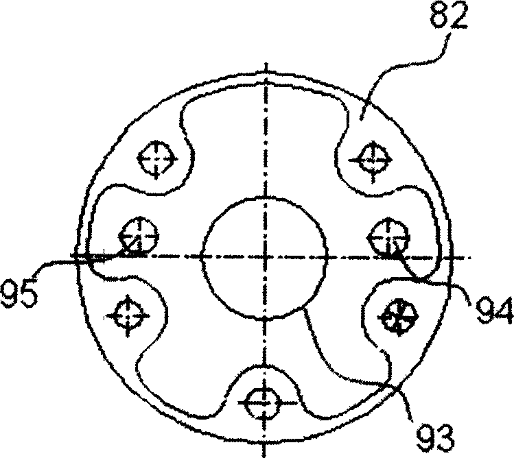
[0022] The shape of the outer layer muffler 84 is a three-lobe type; the distance between the exhaust holes 99 and 100 of the outer layer muffler 84 is set to be equal to an odd multiple of the half-wavelength of the noise frequency to be reduced, and passes through the exhaust hole 99 The phase of the ...


PUM


Abstract

This invention provides a sound suppressor of a compressor including a double layer of an internal sound suppressor and an external sound suppressor with exhaust outlets above the upper bearing with exhaust outlet, among which, the exhaust outlet position of the intenal sound suppressor is set at the place taking the outlet of the upper bearing as the base point rotating counter-clock-wise to the third phase to prolong the flowing path of gas in the inteal layer sound suppressor. The outer sound suppressor is a three flap for increaisng its cavity volume. The distance between two rows of gas holes of the outer suppressor is designed equalizing to the odd times of half-wavelength of the bearing eliminated noise frequency and in opposite phase to the flown sound wav from the hole.

Description

technical field [0001] The invention relates to a compressor, in particular to a compressor muffler which improves the structure of the compressor muffler. Background technique [0002] Rotary compressors are widely used in refrigerators, air conditioners and other electrical equipment. The rotary compressor sucks the gaseous refrigerant evaporated by the evaporator, compresses it to the rated pressure, and then discharges it to the working system of the refrigerant. The rotary compressor can A compressor that continuously sucks in and discharges refrigerant. [0003] figure 1 is a longitudinal sectional view of an existing compressor, figure 1 The compressor indicated in is a rolling rotor rotary compressor, which is represented by figure 1 As shown, the rotary compressor has a closed casing 10, the stator 21 and the rotor 22 of the rotary compressor motor are installed on the top of the casing 10, the eccentric shaft 30 is fixed in the middle of the rotor 22, and the cy...

Claims


Application Information

Patent Timeline
Patent Type & Authority Applications(China)
IPC IPC(8): F04C29/06
Inventor 杨小峰河宗勋王苏豫赵呈国莫洪清刘永利
Owner LG ELECTRONICS (TIANJIN) APPLIANCES CO LTD
Why Eureka
Try Eureka