

Overvoltage on-line sampler for 6-35 KV electric power system
A sampling device and power system technology, applied in emergency protection circuit devices for limiting overcurrent/overvoltage, circuit devices, measuring current/voltage, etc., can solve transient waveform deformities and make it difficult to analyze the exact cause of accidents , equipment insulation level reduction and other issues
- Summary
- Abstract
- Description
- Claims
- Application Information
AI Technical Summary
Problems solved by technology
Method used
Image

Examples
Embodiment Construction
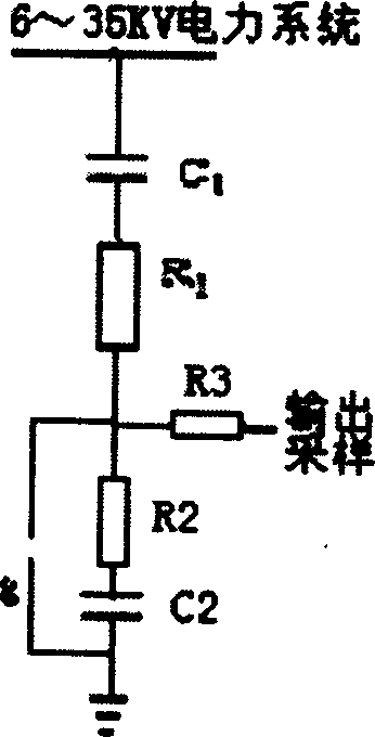
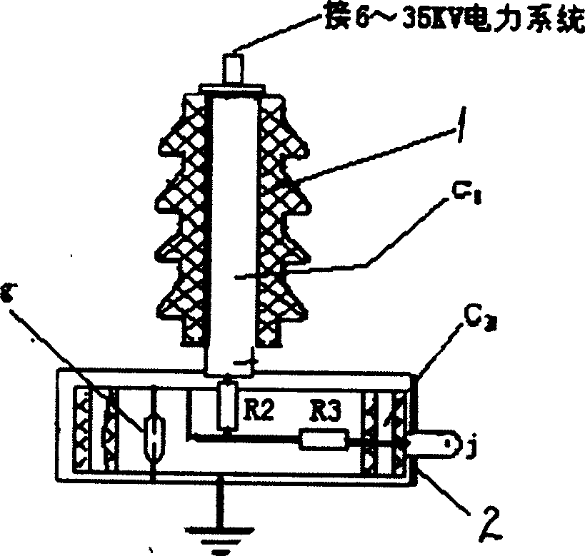
[0012] See attached figure 1 , 2 , in the embodiment, the high-voltage arm includes a high-voltage capacitor C1, a damping resistor R1 and an insulating outer sheath 1, and the low-voltage arm includes a low-voltage capacitor C2, a low-voltage damping resistor R2, a protection gap g, a voltage-dividing output terminal cable connection column J and a metal shielding shell Body 2; the insulating outer sheath of the high voltage arm is a silicone rubber outer sheath, and its creepage distance is not less than 21mm / kv. Several capacitors are coaxially connected in parallel, the surface is coated with an insulating paint layer, and they are installed in a metal shielding shell. A protection gap, that is, a neon tube, is connected in parallel to the low-voltage capacitor of the low-voltage arm. When the low-voltage arm capacitor is overvoltage for some reason, the protection gap The discharge plays a protective role; the output end of the voltage divider is connected to the cable c...
PUM
 Abstract
Description
Claims
Application Information