
Integrated dehumidifier

A dehumidifier and integrated technology, which is applied in heating methods, household heating, lighting and heating equipment, etc., can solve the problems of increased energy consumption of dehumidifiers, poor cooling effect, and increased operating load of compressors. The structure design is simple and reasonable, and the dehumidification effect and the condensation effect are improved.

Inactive Publication Date: 2005-03-02
熊晓强
View PDF0 Cites 12 Cited by
  • Summary
  • Abstract
  • Description
  • Claims
  • Application Information

AI Technical Summary

Problems solved by technology

This kind of heat exchanger distribution, because the heat of the condenser is greater than the cooling capacity of the evaporator, part of the cooling capacity generated by the evaporator is latent cooling and is taken away by condensed water, and the remaining sensible cooling air is used to cool the condenser. If the effect is not good, it will increase the operating load of the compressor and increase the energy consumption of the dehumidifier, especially in high-temperature and high-humidity environments, the energy consumption will be greater, and it is difficult to operate normally under high-temperature conditions, and it is difficult to operate normally under low-temperature conditions. When running under working conditions, the evaporator must stop dehumidification after frosting, and the dehumidification effect is not ideal
Therefore, it is difficult to achieve high-efficiency dehumidification with the distribution of heat exchangers in existing integral dehumidifiers; in addition, the low-temperature condensate discharge method is also likely to cause condensate dripping on the surface of the drain pipe or water tank to fall indoors, and the low-temperature condensate discharge is also a kind of energy loss.

Method used


Image

  • Integrated dehumidifier
  • Integrated dehumidifier
  • Integrated dehumidifier

Examples


Embodiment 1

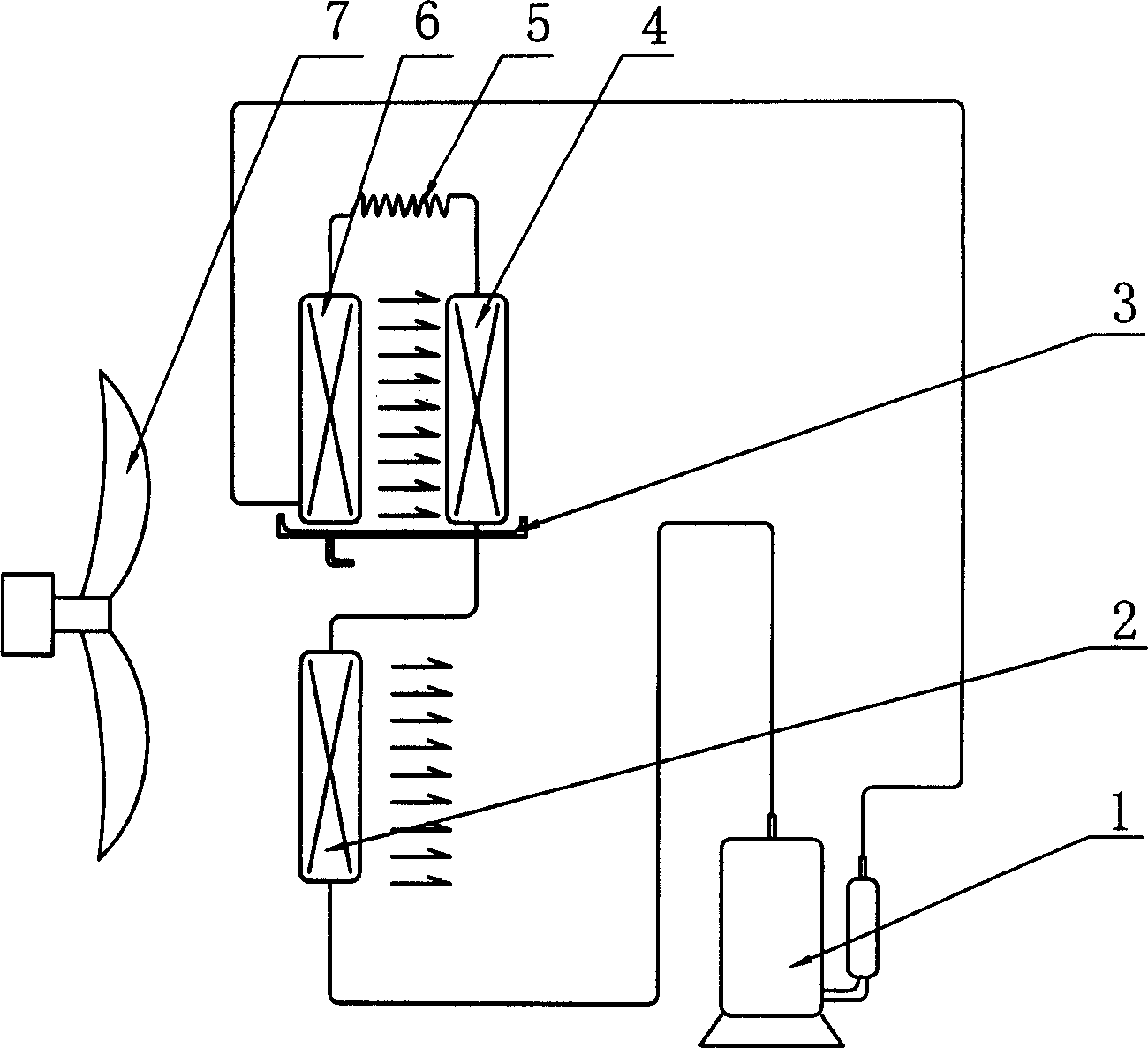
[0026] Embodiment 1, with reference to figure 1 . An integral dehumidifier, comprising a fan blade 7, a water tray 3, and a dehumidification device connected by a compressor 1, a condenser 4, an evaporator 6, and a throttling capillary 5, the exhaust port of the compressor 1 A pre-cooling condenser 2 is arranged between the air inlet of the condenser 4 . Fan blades 7 force a part of the indoor air to pass through the pre-cooling condenser 2, and the other part passes through the evaporator 6 and the condenser 4 for forced convection heat exchange.

[0027] The high-temperature, high-pressure gaseous refrigerant discharged after being compressed by the compressor 1 first enters the pre-cooling condenser 2 for pre-cooling, and then enters the condenser 4 for condensation. The refrigerant becomes a medium-temperature, high-pressure supercooled liquid refrigerant, and then enters the throttling capillary 5 After throttling, it becomes a low-temperature, low-pressure liquid refri...

Embodiment 2

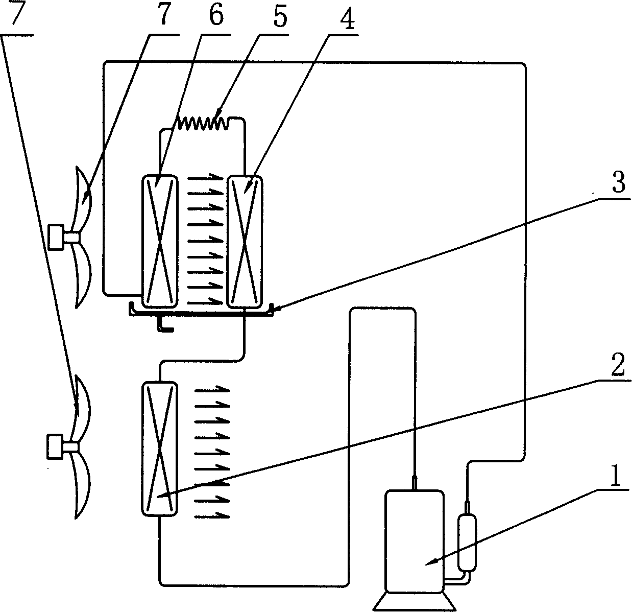
[0028] Embodiment 2, with reference to attached figure 2 . The difference between embodiment 2 and embodiment 1 is that the fan blade 7 is two fan blades, one fan blade 7 forces the indoor air to pass through the evaporator 6 and the condenser 4, and the other fan blade 7 makes the indoor air Forced through precooling condenser 2.

[0029] It is also possible to set the precooling condenser 2 and the fan blade 7 outdoors, and the outdoor air is forced to pass through the precooling condenser 2 by the fan blade 7. If you do not want to increase the indoor temperature, add a row corresponding to the air outlet of the precooling condenser 2 The air duct discharges the heat-exchanged air to the outside and does not enter the room.

Embodiment 3

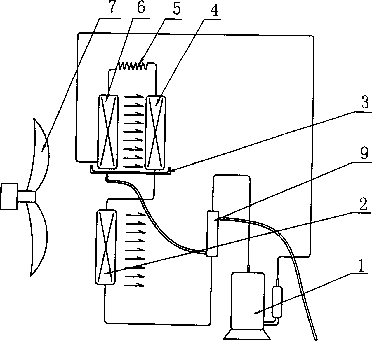
[0030] Embodiment 3, with reference to attached image 3 . The difference between embodiment 3 and embodiment 1 is that a condensed water regenerator 9 is provided between the exhaust port of the compressor 1 and the inlet of the pre-cooling condenser 2, and the condensed water regenerator 9 is connected to the water receiving device through a water pipe. The disks 3 are connected, and the water outlet of the condensed water regenerator 9 is provided with a drain pipe.

[0031] The low-temperature condensed water condensed and removed from the evaporator 6 is collected by the water receiving tray 3 and then enters the water inlet of the condensed water regenerator 9 through the drain pipe, and is then heated by the high-temperature and high-pressure gaseous refrigerant discharged after being compressed by the compressor 1. The water outlet pipe of the water outlet of the regenerator 9 is discharged; and the high-temperature, high-pressure gaseous refrigerant discharged after ...


PUM


Abstract

The invention relates to a dehumidifier dehumidity unit, concretely an entirety type dehumidifier dehumidity unit, comprising fan blade, water collector, compressor, condenser, evaporator, and throttle capillary tube, all of which are linked to construct a dehumidifier dehumidity device, and a precooling condenser is connected in series between the exhaust outlet of condenser and inlet of condenser. The invention whose structure is simple and reasonable can increase condensing effect of the condenser, decrease energy needed and realize high efficient dehumidify, and it can work safely with high efficiency in hot temperature condition; and the added condensation water heat regenerator reuses the power of low temperature condensation water, solving the possible problem that water droplet condensed on waste pipe or water tank falling in room caused by discharging condensation water; the defrosting problem of working under low temperature can also be solved by using defrosting valve or solenoid valve.

Description

technical field [0001] The invention relates to a dehumidifier, in particular to an integral dehumidifier. Background technique [0002] At present, household or commercial integrated dehumidifier systems use two heat exchangers distributed in the front and rear as the condenser and evaporator. The same air flow first passes through the evaporator to remove water and cool down, and then heats up through the condenser to obtain heated drying. At the same time, the refrigerant in the condenser is condensed, and the removed low-temperature water is discharged into the water storage tank or out of the room through the drain pipe. This kind of heat exchanger distribution, because the heat of the condenser is greater than the cooling capacity of the evaporator, part of the cooling capacity generated by the evaporator is latent cooling and is taken away by condensed water, and the remaining sensible cooling air is used to cool the condenser. If the effect is not good, it will incr...

Claims


Application Information

Patent Timeline
Patent Type & Authority Applications(China)
IPC IPC(8): F24F3/14F24F13/22
Inventor 熊晓强
Owner 熊晓强
Learn More