Controlling circuit, controlling method and sequence generator for dc-dc converter

A DC to DC, control circuit technology, applied in the direction of converting DC power input to DC power output, control/regulation system, output power conversion device, etc.

Inactive Publication Date: 2005-03-09
ANALOG INTEGRATIONS CORP
View PDF0 Cites 9 Cited by
  • Summary
  • Abstract
  • Description
  • Claims
  • Application Information

AI Technical Summary

Problems solved by technology

Therefore, the existing PWM DC-DC converter must add additional circuits or switches to

Method used


Image

  • Controlling circuit, controlling method and sequence generator for dc-dc converter
  • Controlling circuit, controlling method and sequence generator for dc-dc converter
  • Controlling circuit, controlling method and sequence generator for dc-dc converter

Examples


Embodiment Construction

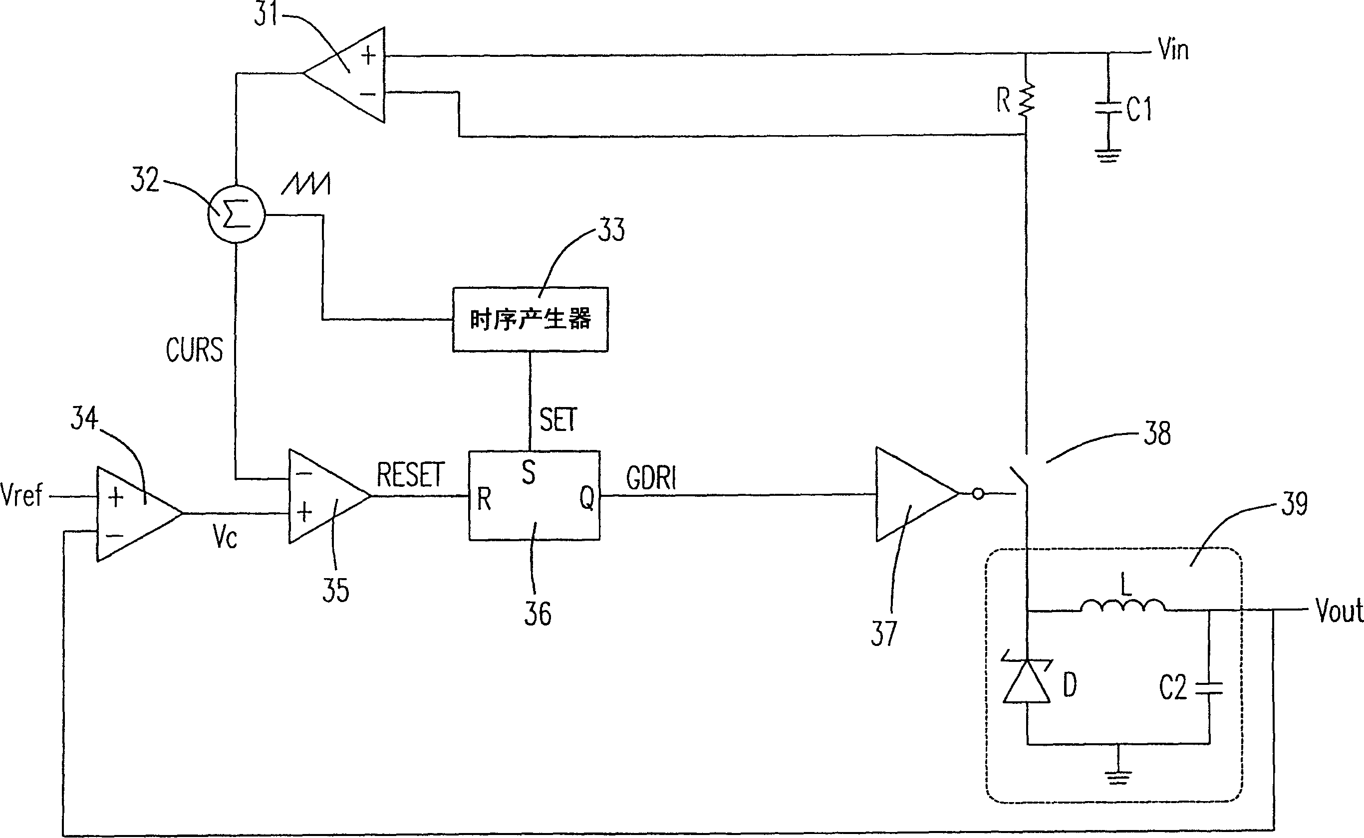
[0065] see image 3 , which is a schematic structural diagram of a control circuit of a pulse width modulation DC-to-DC converter according to a preferred embodiment of the present invention, the control circuit includes a current amplifier 31, a compensator 32, a timing generator 33, and a differential amplifier 34 , a comparator 35 , an R-S flip-flop 36 , a drive circuit 37 , a switch 38 , and a step-down circuit 39 . Wherein, the output terminal of the current amplifier 31 is connected to an input terminal of the compensator 32, the other input terminal of the compensator 32 is connected to the timing generator 33, and the output terminal of the compensator 32 is connected to the comparator The inverting input of device 35. The output terminal RESET of the comparator 35 is connected to the R-S flip-flop 36 . The timing generator 33 is respectively connected to the R-S flip-flop 36 and the compensator 32 , and the driving circuit 37 receives the output GDRI of the R-S flip...


PUM


Abstract

This invention provides a control circuit of a pulse width modulation DC to DC converter, a control mode and a time sequence generator which includes a current amplifier, a compensator, a comparator, a trigger, a time sequence generator connected to the said compensator and the trigger separately for generating modulation signals and set signals, among which, the set signal wave has a widened first low potential pulse at the heavy load state to make the reset signal unable to change to the trigger output signal when the set signal operates, and the wave of the set signal has another widened second low potential pulse when the wave form is at light load stale, so as to set the least starting time action and force the converter in a power-save mode, a driving circuit and a differential amplifier.

Description

technical field [0001] The invention relates to a control circuit and method of a DC-to-DC converter, in particular to a control circuit, a control method and a timing generator of a pulse width modulation DC-to-DC converter. Background technique [0002] Pulse Width Modulation (PWM) technology is often used in the control of DC motors, the voltage stabilization control of power converters, and even the control of DC to AC sine waves. It is the most common method for controlling the speed of DC motors. Its working principle is to change the speed by changing the time ratio of the action, that is, to change the speed by changing the relative time width (Width) of the high potential pulse (Pulse), so this control method is called pulse width modulation technology. [0003] see figure 1 , which is a schematic structural diagram of a control circuit of an existing pulse width modulation DC-to-DC converter, the control circuit includes a current amplifier 11, a compensator 12, a...

Claims


Application Information

Patent Timeline
IPC IPC(8): H02M3/10H02M3/155
Inventor 冯蔚文
Owner ANALOG INTEGRATIONS CORP
Why Eureka
Try Eureka