Liquid fuel evaporation and combustion furnace head

A liquid fuel and combustion furnace technology, which is applied in the direction of liquid heating fuel, burner, heating fuel, etc., can solve the problems of high smoke emission, short warm-up time, short service life, etc., and achieve low smoke emission, preheating The effect of short heating time and long service life

Inactive Publication Date: 2005-03-16
郭建忠
View PDF0 Cites 11 Cited by
  • Summary
  • Abstract
  • Description
  • Claims
  • Application Information

AI Technical Summary

Problems solved by technology

[0003] The purpose of the present invention is to overcome the technical defects of the existing high-power liquid fuel burners in hotel kitchens, such as long preheating time, high noise, high smoke emis

Method used


Image

  • Liquid fuel evaporation and combustion furnace head
  • Liquid fuel evaporation and combustion furnace head
  • Liquid fuel evaporation and combustion furnace head

Examples


Example Embodiment

[0011] The present invention will be further described in detail below with reference to the accompanying drawings.

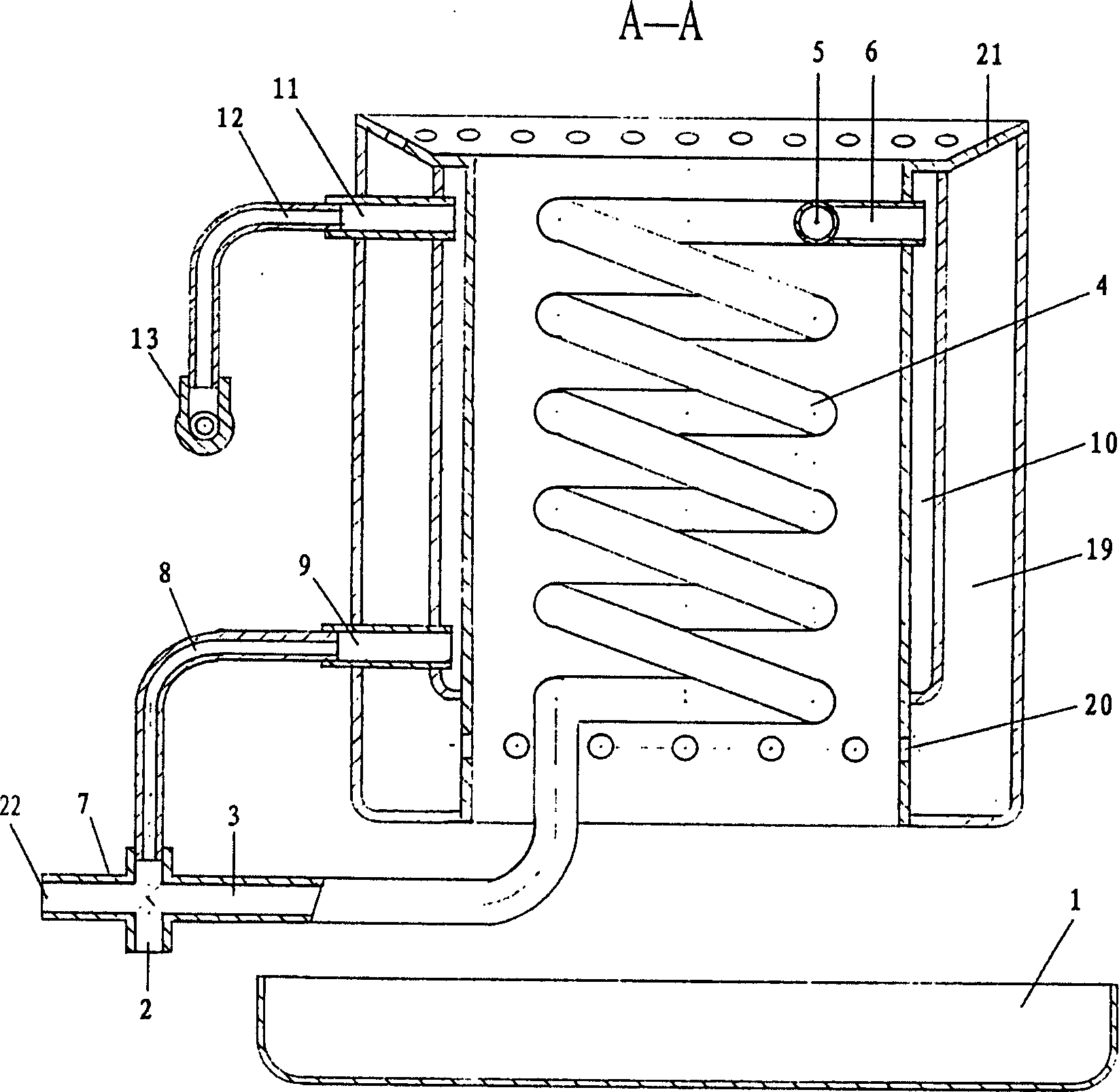
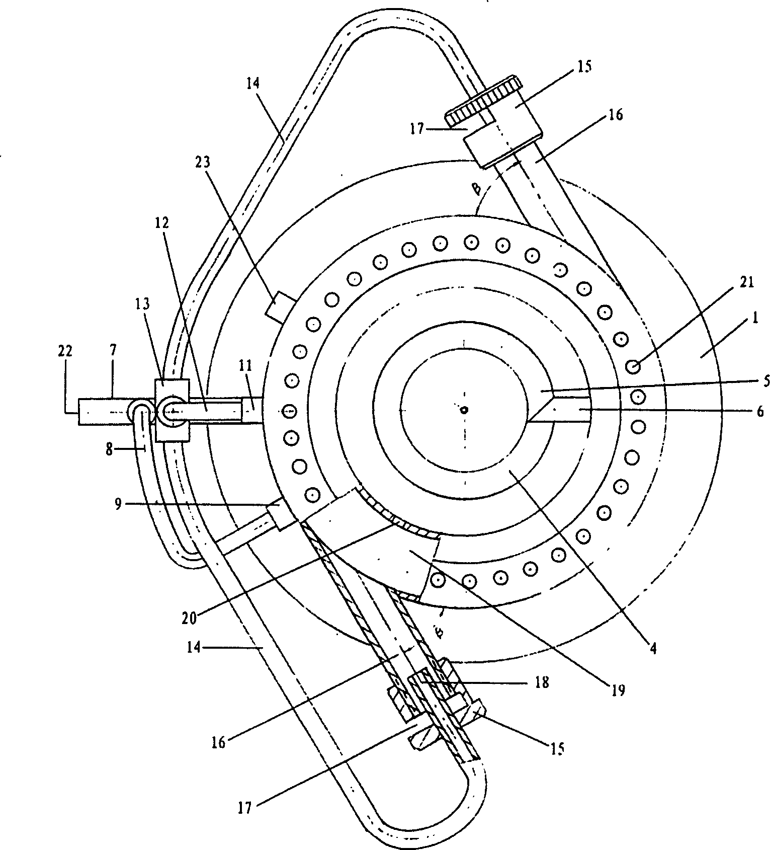
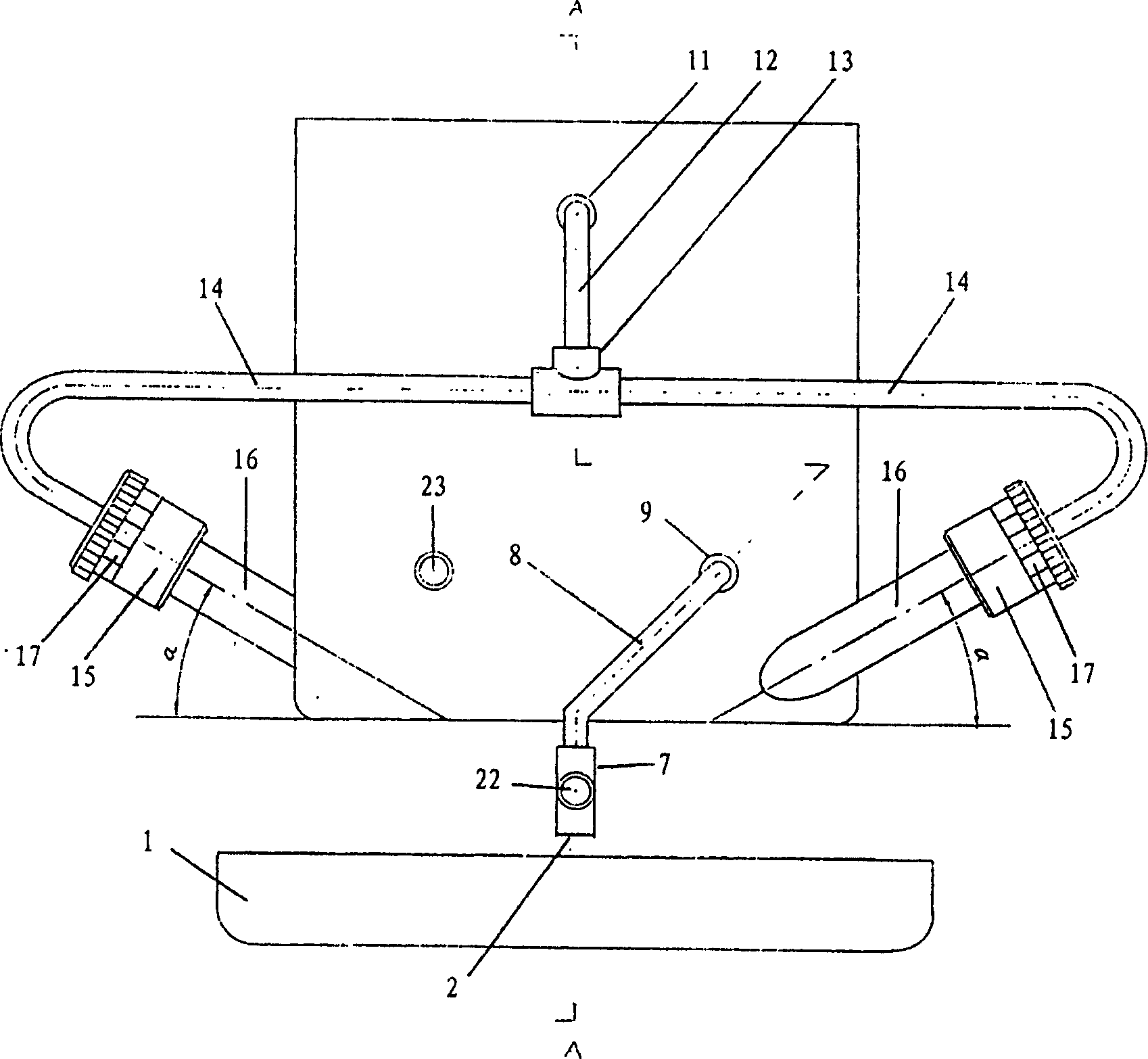
[0012] figure 1 It is a schematic diagram of the front view of the A-A section of the present invention, figure 2 It is a schematic top view of the present invention, image 3 It is a schematic left view of the present invention, including a liquid fuel inlet (2), a preheating coil (4), a vaporization chamber (10), an outlet of the vaporization chamber (11), an air inlet regulating cap (15), a gas nozzle (18), The air suction pipe 16, the swirling air mixing distribution cavity (19), the cooling liquid pipe (8) and the lower inlet of the vaporization cavity (9), the swirling air mixing distribution cavity (19) and the vaporization cavity (10) are all annular The interlayer, the swirl gas mixture distribution chamber (19) is outside, the vaporization chamber (10) is inside, the preheating coil (4) is in the middle of the vaporization chamber (10), and the pre...


PUM


Abstract

This invention discloses a vaporizing furnace head using liquid fuel, including the inlet of liquid fuel, the preheating spiral pipe, the upper inlet of the vaporizing chamber, the vaporizing chamber, the outlet of the vaporizing chamber, the spout of burning gas, the regulating cap of air inlet, the air absorbing pipe, the allocating chamber of swirl flow and mixture air, the cooling fluid pipe, the lower inlet of the vaporizing chamber. Its characteristics are: the vaporizing chamber has the upper and the lower inlets, the vaporizing chamber connects with the spout through the outlet and the guiding pipe, the spout crosses the center hole of the regulating cap and inserts into one end of the air absorbing pipe, the other end of the absorbing pipe connects with the outer wall of the allocating chamber. This invention does not need the exterior wind machinery, and realizes more than 50 kw burning power under the working conditions of low noise, low exhaust and non splash. It is suitable for the kitchen ranges of the hotel, the minitype kitchen range, and other burning equipment.

Description

technical field [0001] The invention relates to a liquid fuel vaporization combustion device, to be precise, it does not need a fan to supply air, and only uses its own liquid vaporization, forced air intake and forced gas mixing functions to achieve low noise, low smoke emission and no splash High-power liquid fuel vaporization combustion burner. Background technique [0002] Existing hotels and kitchens use high-power liquid fuel stoves, no matter the fuel is diesel, kerosene or alcohol-based liquid fuels, the burners are all cast iron, and the liquid fuel must be blown and atomized in the stove by a fan. Combustion, due to the long heating time of the cast iron burner, the loud noise of the fan and the large and uneven particles of liquid fuel atomization, therefore, the stove warms up for a long time, the working environment is noisy, the smoke emission is high, and the fuel splashes out of the stove. contaminate food. Prior art schemes, such as...

Claims


Application Information

Patent Timeline
IPC IPC(8): F23D11/00F24C5/02
Inventor 郭建忠
Owner 郭建忠
Why Eureka
Try Eureka