
High gradient biregion heating directional solidification device

A directional solidification and high-gradient technology, applied in self-solidification, crystal growth, chemical instruments and methods, etc., can solve problems such as low temperature gradient, small speed range, and large system, and achieve the effect of preventing reactions

Inactive Publication Date: 2005-03-23
NORTHWESTERN POLYTECHNICAL UNIV
View PDF0 Cites 9 Cited by
  • Summary
  • Abstract
  • Description
  • Claims
  • Application Information

AI Technical Summary

Problems solved by technology

[0004] In order to overcome the defects of the existing directional solidification equipment, such as low temperature gradient, small range of continuous pulling speed regulation and too large system, the present invention proposes a high-gradient directional solidification device

Method used


Image

  • High gradient biregion heating directional solidification device
  • High gradient biregion heating directional solidification device
  • High gradient biregion heating directional solidification device

Examples


Embodiment Construction

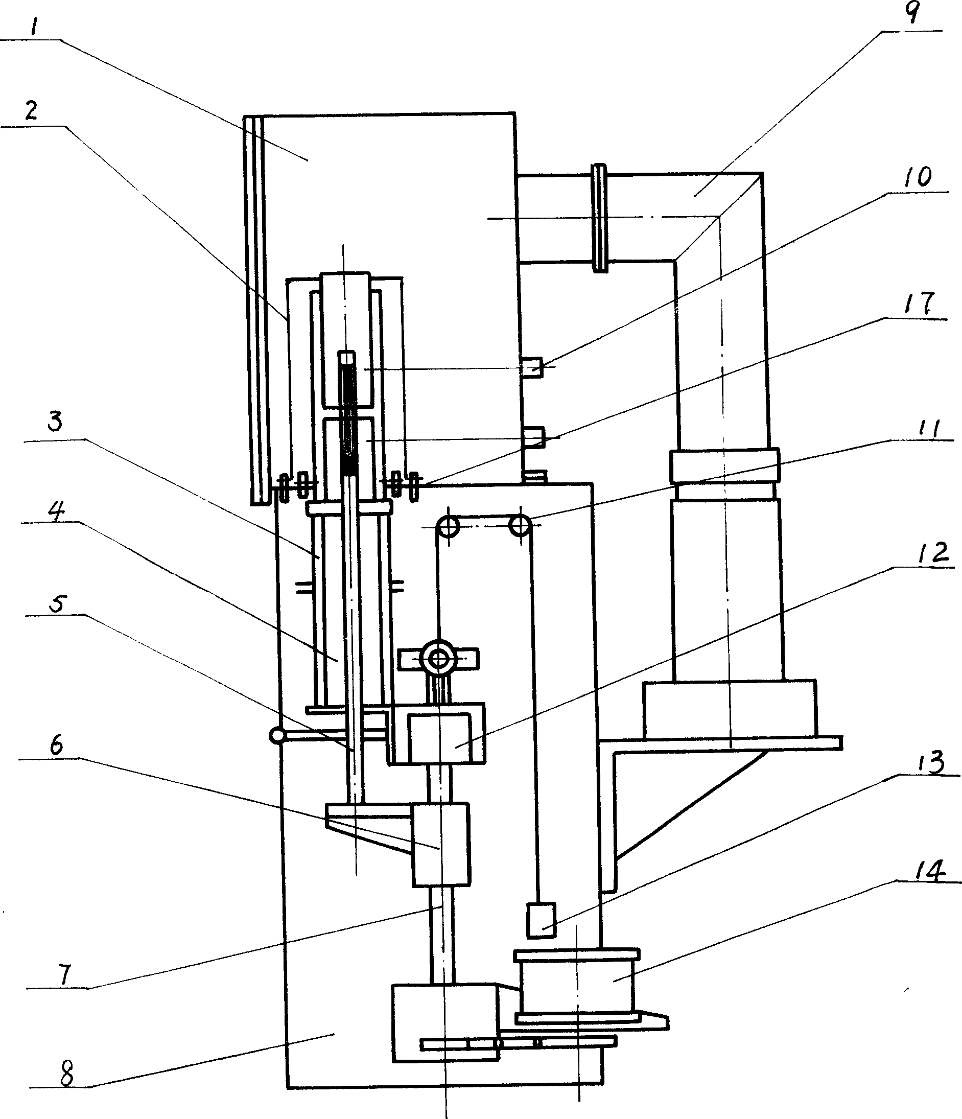
[0024] This embodiment includes a furnace body 1, a heating system, a cooling system, a vacuum system, a drawing system, and a control system. During implementation:

[0025] Furnace body 1: including the bottom plate 17 of the furnace body and the thermocouple 10 for measuring temperature.

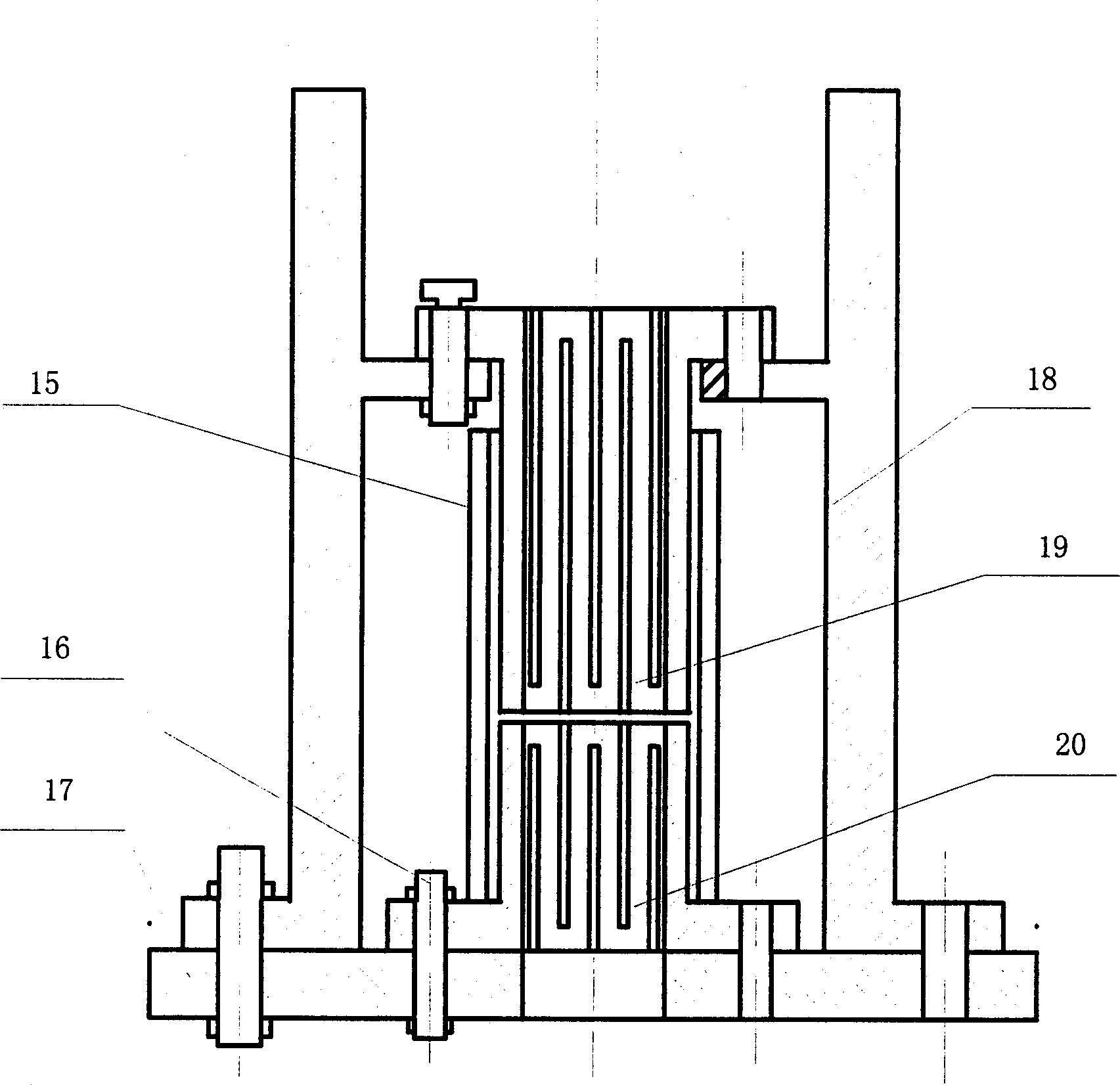
[0026] Furnace body 1 is welded by stainless steel, is installed on the support 8, and its profile is cylindrical, adopts double-layer structure, so that pass through water to cool, and furnace door is a side door, links to each other with furnace body by bolt. There is an observation hole on the top cover of the furnace body, and quartz glass is installed in the hole, and a protective cover is provided. There are two temperature-measuring thermocouples 10 covered with ceramic tubes under the furnace body, and the ceramic tubes are inserted into the heating system 2 . A metal water-cooled electrode 16 is installed at the bottom of the furnace body, which is fastened together with the gra...


PUM


Abstract

A high-gradient directional solidifying apparatus features that its heating system has two heaters positioned respectived at liquid-solid interface and molten region, its drawing unit has mechanical and manual ones which can be electromagnetically switched, and its crystallizer is a dual-layer structure with cooling water jacket.

Description

(1) Technical field: [0001] The invention relates to the field of metal material solidification processing, and is a high-gradient dual-zone heating directional solidification device. (two) background technology: [0002] Directional solidification is a process for directional growth of metal or alloy crystals from a melt, and is used to prepare single crystals, columnar crystals and self-generated composite materials. The directional solidification technology adopts forced one-dimensional heat dissipation, so that the solidification process is oriented along the direction of the temperature gradient, and the directional solidification structure is obtained. Directional solidification technology has experienced the development process of exothermic casting (EP) method, power reduction (PD) method, high-speed solidification (HRS) method and liquid metal cooling (LMC) method. [0003] In theoretical research, in order to systematically investigate the planar, cellular and den...

Claims


Application Information

Patent Timeline
IPC IPC(8): B22D27/04C30B11/00
Inventor 李金山胡锐陈忠伟寇宏超毕晓勤傅恒志
Owner NORTHWESTERN POLYTECHNICAL UNIV
Learn More