Fabricating method of photo crystalline plastic optical fiber

A technology of crystalline plastic and optical fiber, which is applied in the direction of cladding optical fiber, optical waveguide light guide, cutting, etc., can solve the problems of even closing, difficult to preserve optical crystallized optical fiber, optical fiber loss, etc., and achieve the effect of improving control

Inactive Publication Date: 2005-03-23
NEXANS
View PDF0 Cites 2 Cited by
  • Summary
  • Abstract
  • Description
  • Claims
  • Application Information

AI Technical Summary

Problems solved by technology

[0006] The main problem with using solid preforms is that it is difficult to preserve the structure of photocrystallized fibers throug...

Method used


Image

  • Fabricating method of photo crystalline plastic optical fiber
  • Fabricating method of photo crystalline plastic optical fiber
  • Fabricating method of photo crystalline plastic optical fiber

Examples


Embodiment Construction

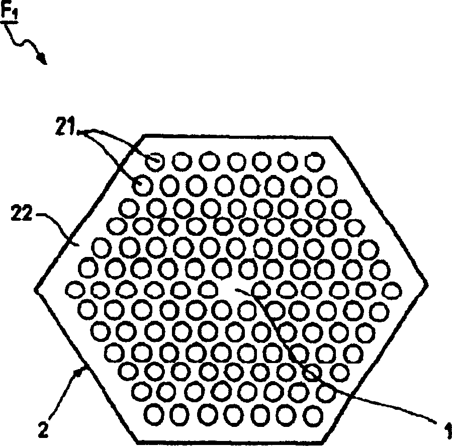
[0035] figure 1 A schematic cross-sectional view of an optical crystallized plastic optical fiber obtained by employing a manufacturing method of a preferred embodiment of the present invention is depicted.

[0036] For example, the optical crystallized plastic optical fiber F1 has a diameter of 100-1000μm and has a hexagonal structure.

[0037] The cladding 2 is formed with a periodic arrangement, for example hexagonal in this embodiment, of cavities 21 which are substantially circular and have a microscopic diameter. The term "microscopic diameter" refers to an average cavity diameter of less than 1 micron, on the order of 1 micron or on the order of 10 microns. For example, in this embodiment, the diameter is 1-30 microns.

[0038] These hollow cavities (without solid or liquid material), for example containing air, are distributed longitudinally in the cladding polymer matrix 22 obtained by UV curing. In this embodiment, the shortest distance between two cavities is sma...


PUM


Abstract

A method of fabricating a photocrystalline plastic optical fiber comprises, for fabricating the cladding, a step of forming a flow by simultaneously injecting a liquid first composition that is a precursor of the cladding polymer and curable by ultraviolet radiation into a first series of holes in an injection plate, and a second composition that is unreactive to the ultraviolet radiation and is selected from a liquid composition and a gas composition into a second series of holes in the plate. The second series of holes have a substantially periodic distribution and each of the holes of the second series has as its closest neighbors holes of the first series. The method further includes a step of irradiating the flow with ultraviolet radiation to form the photocrystalline plastic optical fiber.

Description

technical field [0001] The invention relates to the field of optical fibers, more specifically to a method for manufacturing photocrystalline plastic optical fibers. Background technique [0002] Plastic optical fibers with holes and optically crystallized plastic optical fibers have only recently been known in the art. Such fibers have a cladding comprising a periodic arrangement of cavities with microscopic diameters, containing air, and extending along the Distributed longitudinally in the polymer material cladding matrix. The arrangement periodicity is broken by an artificial defect, which acts as the core of the fiber and is covered by the cladding, and the size and shape of the defect varies according to the arrangement. [0003] Light can be confined within the core as it is guided by the gross internal reflection at the core / cladding interface. In this configuration, the core is generally solid and constructed of the same material as the claddin...

Claims


Application Information

Patent Timeline
IPC IPC(8): G02B6/00B29C48/05B29C48/32B29D11/00G02B6/02G02B6/032
CPCG02B6/02333G02B6/02033B29L2031/60G02B6/02347B29C47/12B29C47/0028B29D11/00663B29C48/11B29C48/05E02B3/14E02D17/205E02D2300/0006E02D2300/0051
Inventor 杰罗姆·福尼尔
Owner NEXANS
Why Eureka
Try Eureka