Automatic device in transverse direction for tracking welding line line by floatation force of welding-torch

An automatic tracking device, horizontal technology, applied in welding equipment, arc welding equipment, manufacturing tools, etc., can solve the problems of low tracking accuracy, complex tracking system, tracking error, etc., to achieve excellent anti-interference ability, simple tracking system, eliminate The effect of tracking error

Inactive Publication Date: 2005-03-30
武汉卓创智能设备有限公司
View PDF0 Cites 14 Cited by
  • Summary
  • Abstract
  • Description
  • Claims
  • Application Information

AI Technical Summary

Problems solved by technology

The above-mentioned technologies have their own advantages, but they all have the following limitations: 1. There is a sensor leading (or lagging) error (transverse tracking accuracy error caused by the sensor not being able to coincide with the center of the welding torch, except for the arc sensing type); 2. The size of the additional sensor is large, which increases the volume and weight of the welding torch, and it is difficult to apply in the occasion where the sensor size is strictly limited; 3. The extraction of the deviation signal generally comes from the surface of the workpiece and the intersection edge between the groove surface and the upper surface edge, and the inhomogeneity deviation information of the groove surface relative to the workpiece surface and edge will be difficult to extract, which will bring a certain system error; 4. This type of tracking system generally has poor anti-interference ability (especially poor anti-electromagnetic field interference) ;5. The tracking system is complex and must be composed of sensors, closed-loop automatic control systems (including hardware and software) and actuators, and the system reliability is relatively low.
This type of tracking technology has the longest application history. Disturbing factors such as arc light, electromagnetic field, smoke and metal vapor, welding spatter, high temperature, workpiece surface state and edge state have little influence on the tracking accuracy, but there are still the following limitations: 1. Tracking The accuracy is low; 2. It is difficult to overcome the obstacles of spot-solid solder joints in the weld; 3. The roughness and surface damage of the groove and weld surface directly affect the stability of the tracking system; 4. There is a leading tracking error; 5. It is usually only suitable for V-shaped, double V-shaped and Y-shaped grooves with large groove face angles, and it is difficult to apply under extremely small groove face angles (β≤2°).

Method used


Image

  • Automatic device in transverse direction for tracking welding line line by floatation force of welding-torch
  • Automatic device in transverse direction for tracking welding line line by floatation force of welding-torch
  • Automatic device in transverse direction for tracking welding line line by floatation force of welding-torch

Examples


Embodiment Construction

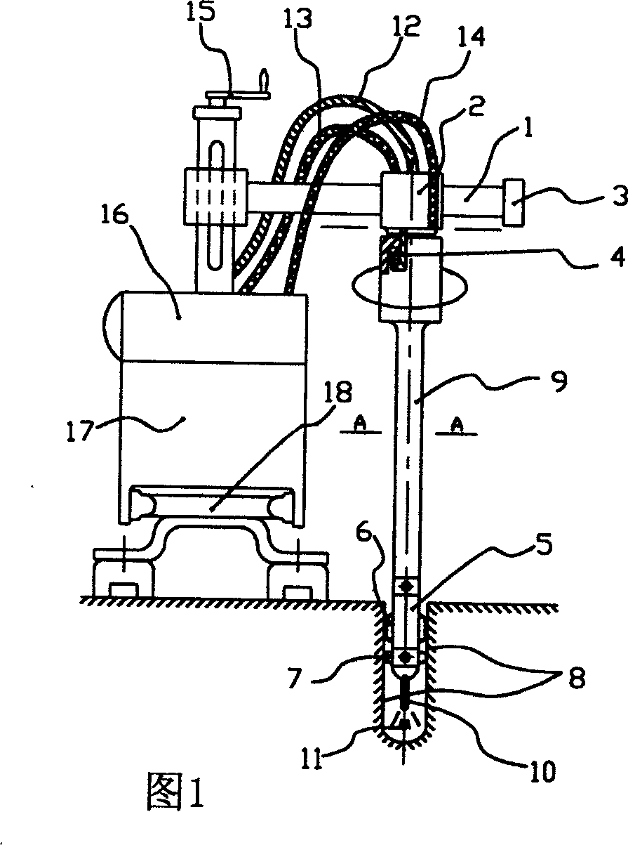
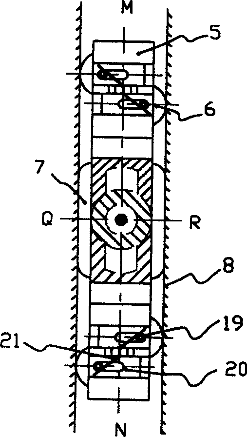
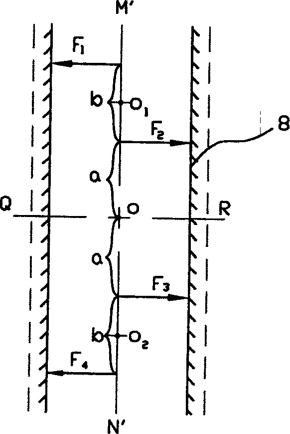
[0015] As shown in Figures 1 to 7, a welding torch floating elastic drive weld seam horizontal automatic tracking device according to the present invention has a welding trolley 17 on which a guide rod 1 for the lateral translation of the welding torch 9 is fixed; the guide rod 1 A sliding sleeve 2 that can move horizontally is connected to the top; the base end of the welding torch 9 and the sliding sleeve 2 are rotatably connected, and the other end is the welding wire outlet end, which is flat, and a plane force couple source that can be installed is fixed on the front and rear sides respectively. The force couple seat body 5 of the component; the force couple source part in each force couple seat body 5 includes two detection rollers 6 that keep the welding wire always at the center line of the welding groove and are respectively attached to the two sides 8 of the welding groove; the detection rollers 6 has the elastic part 21 that makes it can be pressed against the weldin...


PUM

PropertyMeasurementUnit
surface roughnessaaaaaaaaaa
diameteraaaaaaaaaa

Abstract

An automatic transverse weld tracking apparatus for welding torch is composed of a welding carriage with a guide rod on which the welding torch moves transversely, a slide sleeve on said guide rod, a welding torch with a base connected to said slide sleeve and rotary relatively to the slide sleeve and a welding wire outlet, and the front and back force couple bodies with elastic detecting rollers for making the welding wire always on the central line of two bevel surfaces to be welded.

Description

technical field [0001] The invention relates to a welding torch floating elastic force-driven transverse automatic tracking device for welding seams, which is a contact type welding seam transverse self-adaptive automatic tracking device and belongs to the field of welding technology. Background technique [0002] Since the welding technology began to be applied on a large scale in the industrial field in the 1930s, it has roughly experienced the following technological developments: 1. The period of the invention of traditional welding methods (from the early 1930s to the mid-1950s). 2. The perfection of traditional welding methods and the invention of special welding methods (from the mid-1950s to the 1970s). During this period, arc physics and welding metallurgy and other technologies The basic theory is becoming more and more systematic and perfect. On the one hand, the traditional arc welding technology has begun to develop rapidly in the direction of high productivity,...

Claims


Application Information

Patent Timeline
Patent Type & Authority Applications(China)
IPC IPC(8): B23K9/127
Inventor 张富巨张国栋章少华罗传红
Owner 武汉卓创智能设备有限公司
Why Eureka
Try Eureka