

Servo binocular vision sensors on welding robot
A welding robot and binocular vision technology, applied in welding equipment, manipulators, arc welding equipment, etc., can solve problems such as tracking failure, weld detachment, unsatisfactory use, etc., and achieve high practicability
- Summary
- Abstract
- Description
- Claims
- Application Information
AI Technical Summary
Problems solved by technology
Method used
Image

Examples
Embodiment Construction
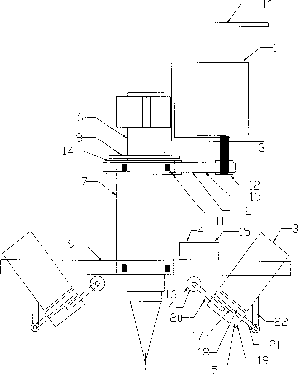
[0012] Such as figure 1 As shown, the present invention includes: a servo motor 1, a synchronous belt transmission system 2, two CCD cameras 3, a pneumatic system 4, a dimming and filtering system 5, an inner hollow shaft 6, an outer hollow shaft 7, an end cover 8 and a flat plate Support 9, channel-shaped support 10 and two bearings 11. The connection relationship is as follows: two CCD cameras 3, pneumatic system 4, light reduction and filter system 5 are fixed on the flat support 9, and the flat support 9 is fixed on the outer hollow shaft 7, between the inner hollow shaft 6 and the outer hollow shaft 7 Two high-precision bearings 11 are arranged, and the outer hollow shaft 7 rotates around the inner hollow shaft 6 through the bearings 11 . The power of the servo motor 1 is transmitted to the outer hollow shaft 7 through the synchronous belt transmission system 2, which drives the CCD camera 3 to rotate around the welding torch, and the synchronous belt transmission system...
PUM
 Abstract
Description
Claims
Application Information