
Method for exchange system for inputting end of two-stage queueing structure

A technology for switching systems and input terminals, applied in transmission systems, digital transmission systems, data exchange networks, etc., can solve problems such as difficult implementation, high complexity of queuing time, and high complexity, so as to reduce difficulty, support service quality, and alleviate The effect of pressure

Inactive Publication Date: 2005-03-30
GRADUATE SCHOOL OF THE CHINESE ACAD OF SCI GSCAS
View PDF0 Cites 3 Cited by
  • Summary
  • Abstract
  • Description
  • Claims
  • Application Information

AI Technical Summary

Problems solved by technology

The advantage of the first method is that queuing is relatively simple, but because there are often too many queues, the time complexity of the central scheduling algorithm is relatively high due to the use of weighted matching; while the second method is just the opposite, only M queues are scheduled, and the central The scheduling algorithm is relatively easy to implement, but since the weight of data packets must be dynamically calculated in each time period, and the one with the largest weight must be placed at the head of the queue, that is, the queue must be dynamically inserted in each time period, and the time complexity of queuing is relatively high. difficult to realize
Therefore, these methods have problems such as high complexity and difficult implementation.

Method used


Image

  • Method for exchange system for inputting end of two-stage queueing structure
  • Method for exchange system for inputting end of two-stage queueing structure
  • Method for exchange system for inputting end of two-stage queueing structure

Examples


Embodiment Construction

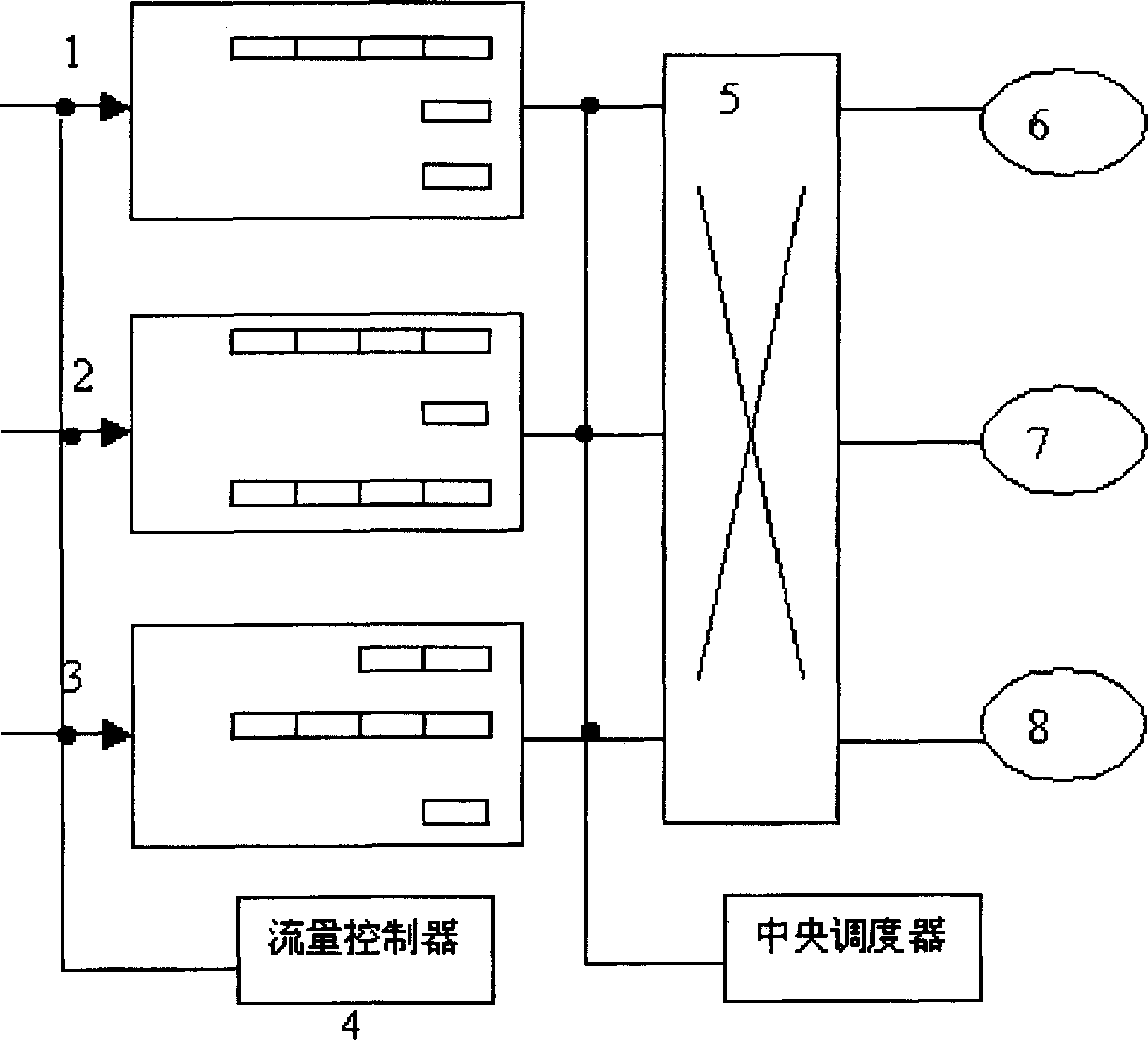
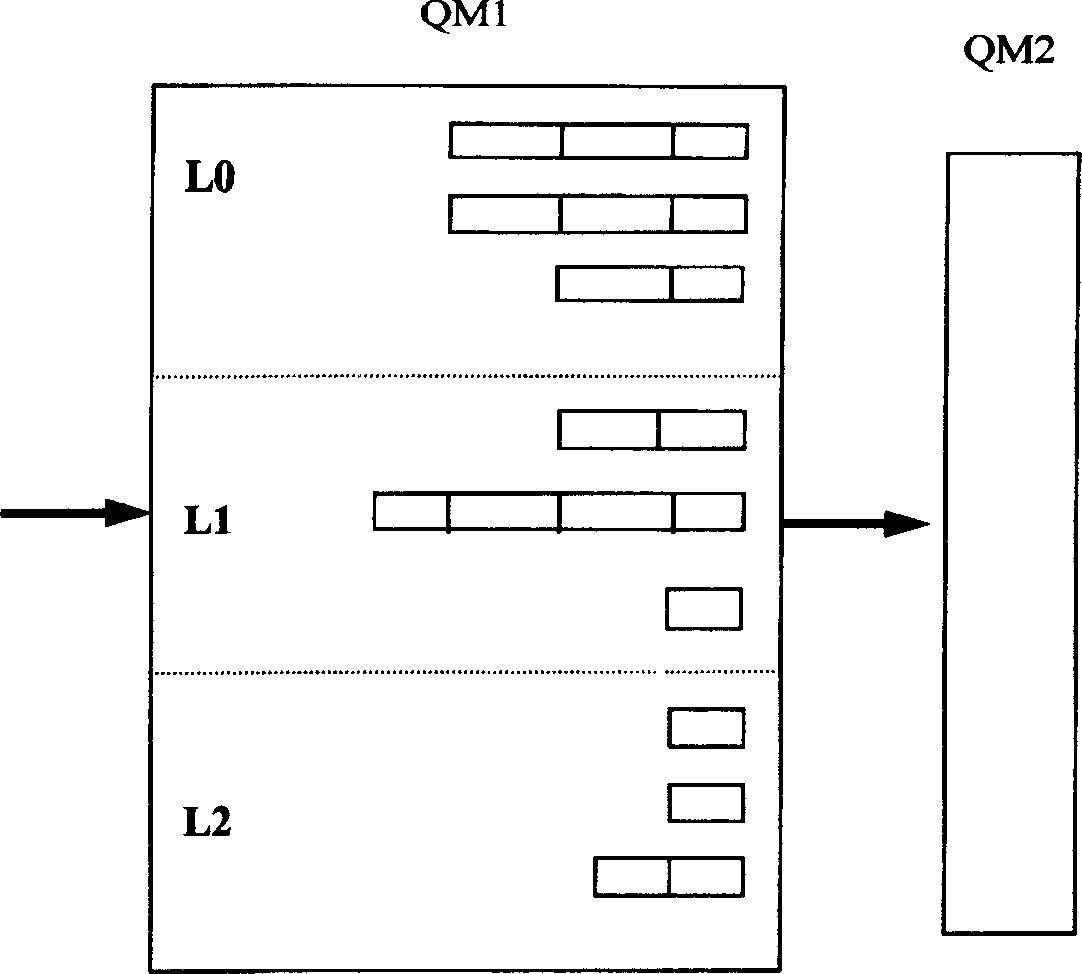
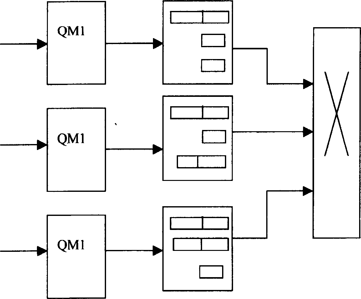
[0025] The embodiment of the present invention provides a specific method of queuing at the input end. For the convenience of description, the first level of queuing in the present invention is called QM1 (Queue Manager 1), and the second level of queuing is called QM2 (Queue Manager 2). . The time of the system will be discrete into discrete time periods. Input queuing means that data packets arriving at the system are queued in the input buffer storage area to be scheduled for transmission, and the time period is divided into "system internal time period" and "system external time period". Data packets arrive at the input of the system only at the beginning of the "system external time period". Data packets arriving at the input end will be dispatched to the corresponding destination by the scheduling method at the end of each "system internal time period", and each data packet will be transmitted to the corresponding destination at the end of each "system internal time period" ...


PUM


Abstract

NXM queuing system in switching system contains N input ends and M destination ends. There are switching unit, flow controller and system central dispatcher. Characters are: (1) queuing data packets in two stages is carried out in storage buffer area at input end; at first stage, based on priorities, data packets reached to each input end in system are sorted to L classes, L is a positive integer larger than 1 given in advance; (2) based on each class, queuing is carried out according to destination; (3) through simple and effective dispatch algorithm, data packets in queues in first stage are sent to queues in second stage according to priorities of destination ends; (4) under control of quick dispatch of central dispatcher, data packets through switching unit reach to destination end of the system. The invention supports quality of service, lowers difficulties of bottleneck of central dispatch. The method is applicable to high-speed router in large scale and other switchboard.

Description

Technical field [0001] The invention relates to a method for controlling data packets flowing through a network communication system, in particular to a method for a two-stage queuing structure at the input end of a switching system. Background technique [0002] At present, the information network is developing at an extremely rapid rate. The data flow on the Internet is increasing at a rate of 30% per month. The amount of information transmitted on the information network is already astronomical, and the development of the next generation network The overall trend is bound to be the rapid growth of bandwidth and the continuous improvement of speed. The switching capacity of the core router, the central node, will inevitably increase by tens to hundreds of times; on the other hand, the level of human use of information networks is constantly deepening. , Users' requirements for service quality are also rapidly increasing. In recent years, service quality assurance has become a m...

Claims


Application Information

Patent Timeline
IPC IPC(8): H04L12/24H04L12/28H04Q3/64
Inventor 郭田德陈玉福高随祥徐德举张敏洪张三国尹红霞华光杨德庄
Owner GRADUATE SCHOOL OF THE CHINESE ACAD OF SCI GSCAS
Learn More