Detection method for resonance frequency of resonant type piezoelectric microsensor

A resonant frequency, micro-sensor technology, applied in frequency measurement devices, measurement of force by measuring the frequency change of stressed vibration elements, etc. Effect

Inactive Publication Date: 2005-04-06
FUDAN UNIV
View PDF0 Cites 19 Cited by
  • Summary
  • Abstract
  • Description
  • Claims
  • Application Information

AI Technical Summary

Problems solved by technology

These large devices are relatively difficult to integrate on microsensor chip

Method used


Image

  • Detection method for resonance frequency of resonant type piezoelectric microsensor
  • Detection method for resonance frequency of resonant type piezoelectric microsensor
  • Detection method for resonance frequency of resonant type piezoelectric microsensor

Examples


Embodiment Construction

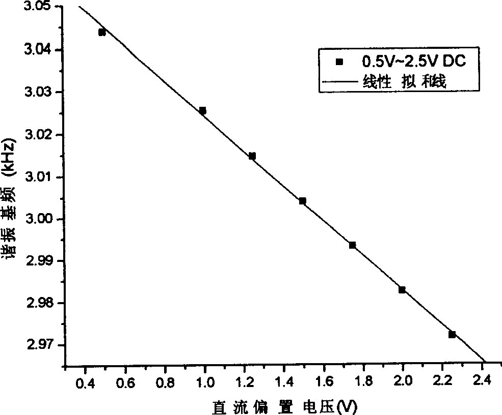
[0023] The self-developed resonant PZT micro-cantilever sensor is detected by using the method of the invention. The dimensions of the PZT microbeam structure are 860 microns long, 300 microns wide, and 2 microns thick. PZT material is made of Korean INOSTEK  The company's commercial products are prepared by the sol-gel process, and the precise thickness of the PZT layer in the microbeams is 210nm. After scanning the DC bias voltage of the excitation signal, it is found that the DC bias voltage and the resonant frequency of the PZT microbeam are related by a second-order function. When the DC bias electric field is less than 1×10 7 At V / m, there is a linear region between the DC bias voltage and the resonant frequency of the PZT microbeam. See image 3.

[0024] The experimentally measured relationship between the two is:

[0025] f=3.06598-0.04167U

[0026] f is the resonant frequency (kHz), and U is the DC bias voltage (V) applied to the PZT. From this measurement r...


PUM


Abstract

This invention belongs to piezoelectric sensor technique field and in detail is a resonance piezoelectric sensor resonance frequency measurement method, which is the following: according to the linear relationship between direct bias voltage and piezoelectric micro structure in certain range of the excitation signal, it uses exciting signal to excite the piezoelectric structure and uses data collection card to get maximum range value and direct bias voltage V#-[DC] and V#-[DC1] relative to the maximum range value; then it gets the resonance frequency altered value according to differential value of V#-[DC] and V#-[DC1].

Description

technical field [0001] The invention belongs to the technical field of resonant piezoelectric microsensors, and in particular relates to a method for detecting the resonant frequency of a resonant piezoelectric microsensor. Background technique [0002] Piezoelectric microsensors were first used to measure microforces, such as acceleration sensors, angular velocity sensors, and atomic force microscopes (AFM). In recent years, the application of resonant piezoelectric microsensors in the detection of chemical gas molecules has attracted more and more attention due to their extremely high sensitivity. The detection principle of the resonant piezoelectric microsensor is generally that when the piezoelectric microstructure absorbs chemical gas molecules, the resonant frequency of the microstructure also changes, so the detection of the change of the resonant frequency of the microstructure also detects the chemical gas molecules. concentration. Usually, the signal detection sy...

Claims


Application Information

Patent Timeline
IPC IPC(8): G01L1/10G01R23/02
Inventor 王军军周嘉黄宜平
Owner FUDAN UNIV
Why Eureka
Try Eureka