
Automatic tracking protector for earth leakage and operation method thereof

An automatic tracking and protector technology, applied in the direction of automatic disconnection emergency protection devices, emergency protection circuit devices, electrical components, etc., can solve problems such as failure, economic loss, and normal leakage, so as to expand application occasions and improve investment luck rate, guarantee the effect of correct protection

Inactive Publication Date: 2005-04-06
HEBEI UNIV OF TECH
View PDF5 Cites 25 Cited by
  • Summary
  • Abstract
  • Description
  • Claims
  • Application Information

AI Technical Summary

Problems solved by technology

However, the leakage situation in the actual power grid is more complicated, not only the normal leakage in different power grids is different, sometimes the difference is relatively large; even the normal leakage in the same power grid is not always the same, it will change with the change of environmental conditions , especially in the dry season and the wet season, the normal leakage current of the power grid is quite different
It is difficult to achieve correct fault leakage protection when using a fixed leakage action current threshold in the power grid
If the leakage action current threshold used in the power grid is small, although the fault leakage protection is realized, the normal leakage current of the power grid increases in the wet season, and the leakage protector will often operate, reducing the operation rate of the power grid, and even Cause economic losses to users; if the leakage action current threshold adopted in the power grid is relatively large, the commissioning rate of the power grid in the wet season is increased, and in the dry season, the normal leakage current of the power grid is reduced. In this case, if Fault leakage, the leakage protector may not operate, affecting people's electricity safety and causing economic losses
Although in the prior art, some protectors with multi-level leakage operating current thresholds are used, a smaller leakage operating current threshold is set when the normal leakage current is small, and a larger leakage operating current is set when the normal leakage current is large. Threshold, to a certain extent, improves the application effect of the leakage protector, but because the set leakage action current threshold will not change automatically, when the normal leakage of the power grid changes greatly due to changes in climate or other environmental conditions, the leakage protector will still Working under the original leakage action current threshold, it still cannot provide correct protection for fault leakage current
For general users, they cannot know the normal leakage current in the power grid, especially when the normal leakage current in the power grid changes with the environment, and users cannot set the leakage action current threshold according to the actual situation
CN 99120647.9 and CN 99230358.3 disclose an "intelligent controller for a communicable molded case circuit breaker", in which the designed phase-locked loop frequency tracking circuit is used to automatically track frequency changes, but cannot be used to automatically track changes in normal leakage current of the power grid. And its frequency tracking circuit is complicated; CN 93244614.0 discloses an "intelligent multifunctional load controller", although a tracking memory circuit is mentioned, which is suitable for limiting illegal electricity consumption such as electric heating appliances, but it has nothing to do with leakage protection; in CN 98118285.2 And CN 98245498.8 disclosed "Microcomputer Digital Intelligent Leakage Protector", although it has the characteristics of automatic tracking of leakage, but only for the phase and amplitude detection technology, there is no distinction between normal leakage and fault leakage of the power grid
In short, none of the existing leakage protectors can overcome the contradiction between the operation rate of the power grid and the safety of electricity consumption.

Method used


Image

  • Automatic tracking protector for earth leakage and operation method thereof
  • Automatic tracking protector for earth leakage and operation method thereof
  • Automatic tracking protector for earth leakage and operation method thereof

Examples


Embodiment

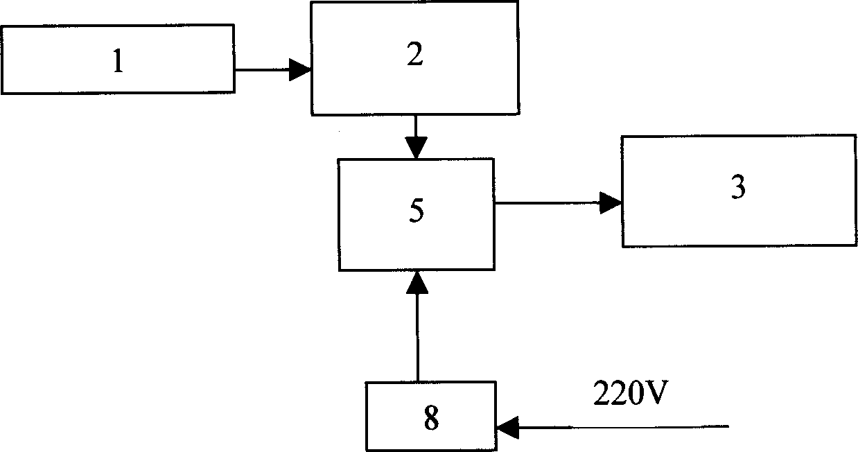
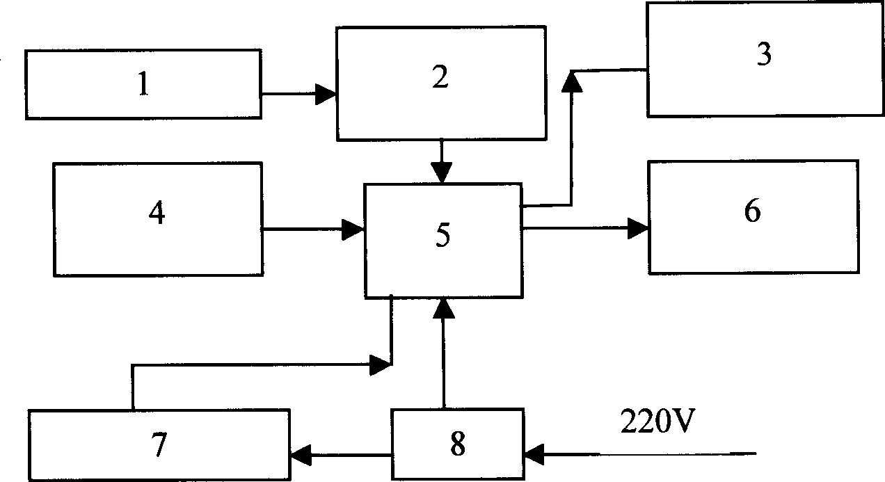
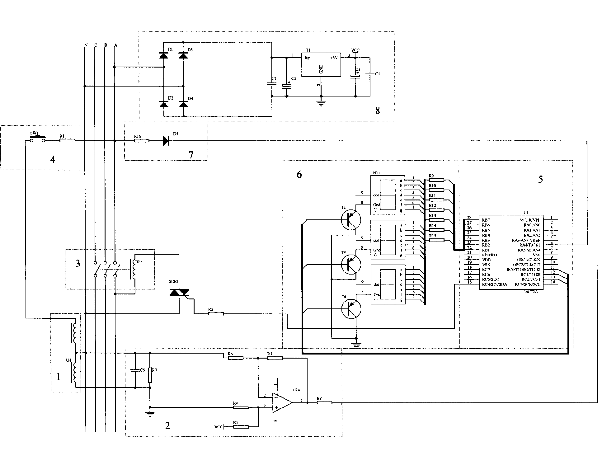
[0027] figure 1 It shows that the leakage automatic tracking protector of the present invention comprises a single-chip microcomputer (5), a zero-sequence current transformer (1), a leakage signal amplifying circuit (2), a power supply (8) and an air circuit breaker or relay (3). The leakage signal detection circuit of the leakage automatic tracking protector of the present invention is composed of a single-chip microcomputer (5), a zero-sequence current transformer (1), a leakage signal amplification circuit (2) and a power supply (8). The operation method for them to realize the leakage automatic tracking and protection process is: the zero-sequence current transformer (1) detects the leakage current in the power grid, and converts the leakage current into a voltage signal and inputs it to the leakage signal amplification circuit (2); The leakage signal amplified by the circuit (2) is directly input into the single chip microcomputer (5); Angle change, to judge whether the ch...


PUM


Abstract

This invention relates to a drain self-tracing protector and its operation method, which comprises air breaker or relay, single machine, zero current mutual inductance, drain signal amplifying circuit and power, wherein the single comprises the following steps: first to initiate; second to measure the current range and phase angle; third to figure out drain changes; fourth to judge whether drain changes Is more than ten percent of drain action valve value; fifth to judge the sustain time of less than ten percent of drain action valve; sixth to change action valve. When the drain current amounts to or exceeds the drain action valve , the single machine sends out drain release order to trigger controllable silicon to activate the air breaker or relay to cut off the fault circuit to protect the fault drain.

Description

technical field [0001] The technical solution of the present invention relates to an automatic disconnection emergency protection circuit device which directly responds to unexpected changes deviated from normal electrical working conditions, specifically a leakage automatic tracking protector and its operating method. Background technique [0002] Leakage protection technology is widely used in low-voltage power grids to prevent leakage fires and protect people from electric shock. With the improvement of people's awareness of electricity safety, the application field of leakage protection technology is still expanding. However, leakage protection and grid power supply have become a pair of contradictions in people's electricity consumption. From the perspective of electricity safety, it is hoped that once leakage occurs, the leakage protector will act to prevent leakage fire and personal electric shock in time; from the perspective of the operation rate of the power grid,...

Claims


Application Information

Patent Timeline
IPC IPC(8): H02H3/32H02H3/34
Inventor 李奎陆俭国武一王景芹李志刚骆燕燕赵靖英
Owner HEBEI UNIV OF TECH
Learn More