Optical fiber connector

A technology of optical fiber connectors and optical fiber joints, applied in the coupling of optical waveguides, etc., can solve the problems of inability to achieve optical coupling of optical components, formation of guide groove extension, and insertion of optical fiber joints 6a, so as to improve the efficiency of assembly and testing, and strengthen the control system. Accurate, simple structure effect

Inactive Publication Date: 2005-05-04
LITE ON OPTO TECH (CHANGZHOU) CO LTD +1
View PDF0 Cites 5 Cited by
  • Summary
  • Abstract
  • Description
  • Claims
  • Application Information

AI Technical Summary

Problems solved by technology

The optical fiber connector 5a is to increase the area of ​​the elastic shutter 54a to close the guide groove, the guide groove will not be formed along the rear direction of the optical fiber insertion hole, but can only be formed near the entrance of the optical fiber insertion hole, so that The optical fiber connector 6a cannot be stably inserted according to the guidance of the guide groove, and cannot achieve a good optical combination with the optical component; wherein, the elastic shield 54a will be bent due to the entry of the optical fiber connector 6a, which Elastic fatigue is prone to occur at the bend, and it will not be able to return to the closed state and lose its effect
[0010] At the same time, none of the above-mentioned third known technology, fourth known technology, and fifth known technology can limit the insertion depth of the optical fiber connector 6a, which may cause contact friction between the end face of the optical fiber and the surface of the optical component, resulting in scratches and Reduce the intensity of the optical signal to be transmitted, thereby affecting the system's misjudgment of the signal

Method used


Image

  • Optical fiber connector
  • Optical fiber connector
  • Optical fiber connector

Examples


Embodiment Construction

[0055] The present invention provides an optical fiber connector, which uses a U-shaped cover to cover the main body, and inserts the left and right side plates of the U-shaped cover with the card slots provided on the upper and lower edges of the main body. The type cover has a socket portion extending downwards from its top edge to integrally form a dustproof cover, and the two side plates have abutting surfaces that closely fit the card slot along the upper and lower edges; thereby, the main body and the The cover can be combined into an optical fiber connector with the dustproof cover. Its structure is simple and strong, and it is convenient to use and test. It can improve the efficiency of assembly and testing, reduce the cost, and avoid the assembly steps caused by the separate dustproof cover. Complicated to avoid the danger of children eating by mistake.

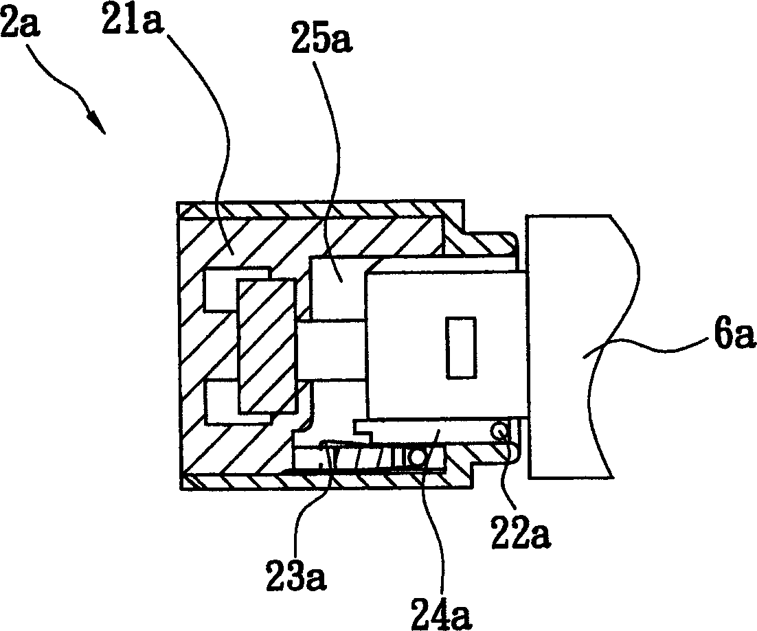
[0056] Please refer to Figure 6A to Figure 6C , the present invention provides an optical fiber connector 7 , wh...


PUM


Abstract

This invention is a kind of optical fiber connector that used on optical fiber splice. It comprises main body and the U style mantle that cover the body. Slots are set on the bottom and top ora terminalis. The U style mantle comprises jack section and the left and right two sides plate that used to connect the section. The jack section has a dust cap from its top to the bottom, and the two sides plate has contact surface that close fit the slot along the top and bottom ora terminalis. The optical fiber connector is rotary open, and the structure is simple and firm. It can raise the assembling and testing efficiency, reduce the cost, and reach to the function of preventing the dust and foreign matter. It can restrict the insert depth of the optical fiber splice, and enhance the collimation between optical fiber splice and luminous module or module that receives the light.

Description

technical field [0001] The invention relates to an optical fiber connector, in particular to an optical fiber connector for coupling optical information to an optical fiber. Background technique [0002] With the development of optical fiber communication, the demand for optical fiber connectors is also increasing. Optical components are usually installed in optical fiber connectors. In order to prevent dust or foreign objects from affecting the optical performance of optical In case of injury to the operator's eyes, it is necessary to cooperate and close the entrance of the optical fiber connector. [0003] Please refer to figure 1 , is the optical fiber connector 1a of the first known technology, which uses a dustproof plug 12a structure to achieve the above purpose, and when the connector body 11a is not docked with other optical devices, the dustproof plug 12a is assembled on the side of the connector body 11a The optical fiber insertion hole is used to close the optic...

Claims


Application Information

Patent Timeline
Patent Type & Authority Applications(China)
IPC IPC(8): G02B6/36
Inventor 王坤生
Owner LITE ON OPTO TECH (CHANGZHOU) CO LTD
Why Eureka
Try Eureka