Vertical light catalytic air purifier

An air purifier and photocatalytic technology, applied in chemical instruments and methods, heating methods, air conditioning systems, etc., can solve the problems of small air passing area of ​​pollutants, inability to eliminate gas at one time, complex structure of photocatalytic chamber, etc., and achieve increased Large processing capacity, good removal effect, and the effect of improving purification efficiency

Inactive Publication Date: 2005-05-11
中投亿星新能源投资有限公司
View PDF1 Cites 43 Cited by
  • Summary
  • Abstract
  • Description
  • Claims
  • Application Information

AI Technical Summary

Problems solved by technology

The structural design of the purifier has the following problems: (1) The air-passing area of ​​pollutants is small under the same volume of the purifier; (2) The high-voltage electrostatic precipitator will generate ozone, which

Method used


Image

  • Vertical light catalytic air purifier
  • Vertical light catalytic air purifier
  • Vertical light catalytic air purifier

Examples


Embodiment Construction

[0020] The present invention will be described in further detail below in conjunction with the accompanying drawings and embodiments.

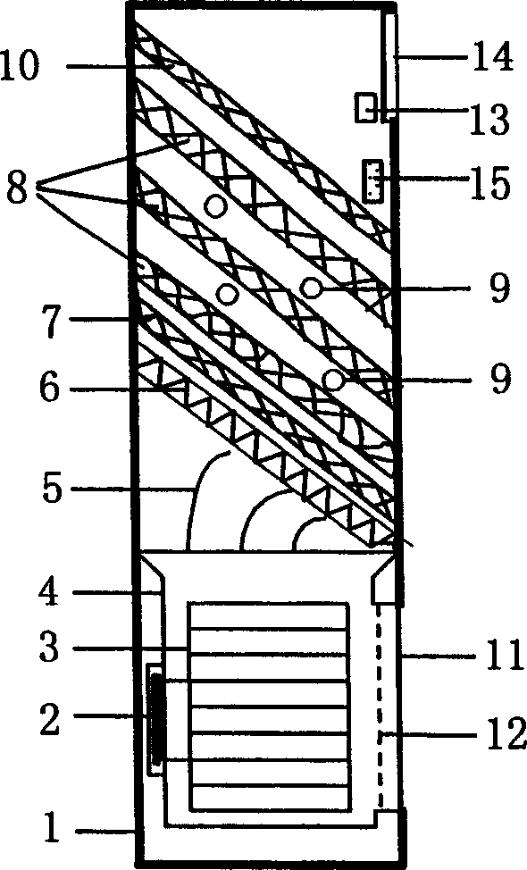
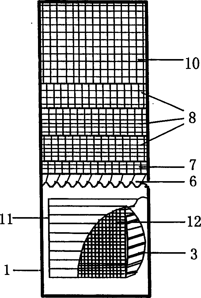
[0021] The implementation of the technical solution of the present invention refers specifically to figure 2 , image 3 . On the basis of the prior art, the structural feature of the present invention is that there is a deflector 5 on the top of the socket shell 4, and the airflow direction through the deflector 5 is perpendicular to the medium-efficiency filter 6 placed obliquely, and the medium-efficiency filter 6 , The plasma dust collector 7, the photocatalytic honeycomb filter screen 8 and the horizontal plane are at an angle of 45 degrees, which improves the contact area between the pollutants and the catalyst. Negative ion generator 13 is arranged near the airflow outlet to increase the concentration of negative ions in the air. figure 2 The photocatalytic purification unit includes three photocatalytic honeycomb filter screens 8 a...


PUM

PropertyMeasurementUnit
Dominant wavelengthaaaaaaaaaa

Abstract

A vertical photocatalytic air purifier is composed of casing with air inlet, primary net filter, through-flow fan, motor for fan, airflow guiding volute, air outlet, circuit board, secondary net filter, an guide plate, plasma duster, photocatalyzing unit consisting of photocatalytic cellular net filter and UV lamp, activated carbon net filter, and negative ion generator.

Description

Technical field: [0001] The invention belongs to the technical field of air purifiers, in particular to the technical field of manufacturing a multifunctional air purifier. Background technique: [0002] The source of indoor air pollution includes dust, fiber, odor, odor, bacteria, virus and other substances, but the harm to human health mainly lies in the indoor suspended inhalable particles. This is because bacteria, spirochetes, viruses and other microorganisms that cause damage to human health, although their size is only between 0.01 and 10 microns, they cannot exist alone in the air and often adsorb on the surface of particles several times larger than them. Traditional air purifiers use air blowers to pass air through porous filter materials (materials such as non-woven fabrics, filter paper, fiber or foam filter materials), thereby separating pollutants from the air to achieve the purpose of purification, or through corona The discharge makes the pollutants in the a...

Claims


Application Information

Patent Timeline
IPC IPC(8): B01D53/86F24F3/16
Inventor 马重芳鹿院卫吴玉庭王伟
Owner 中投亿星新能源投资有限公司
Why Eureka
Try Eureka