Method of making optical fiber by high speed drawing

An optical fiber, high-speed technology, applied in the field of high-speed drawing optical fiber, can solve the problem of unsolved problems such as extrusion deformation of coated optical fiber, and achieve the effects of improving micro-bending performance, reducing micro-bending attenuation, and promoting curing.

Active Publication Date: 2005-05-25
SHANTOU HIGH TECH ZONE AOXING OPTICAL COMM EQUIP
View PDF3 Cites 7 Cited by
  • Summary
  • Abstract
  • Description
  • Claims
  • Application Information

AI Technical Summary

Problems solved by technology

This method does not solve the problem that the coated optical fiber is squeezed and deformed by the rubbing device

Method used


Image

  • Method of making optical fiber by high speed drawing
  • Method of making optical fiber by high speed drawing
  • Method of making optical fiber by high speed drawing

Examples


Embodiment 1

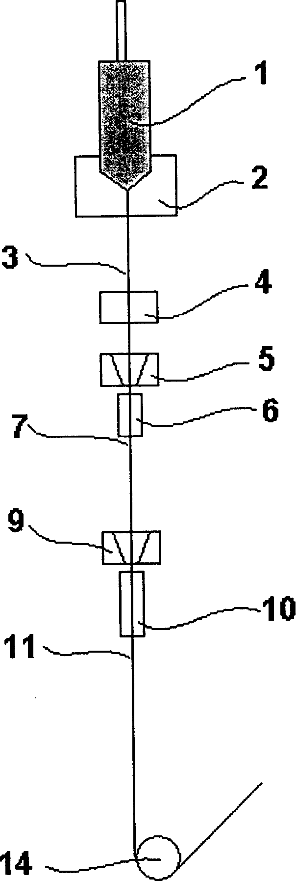
[0026] During the optical fiber drawing process, the outer diameter of the bare optical fiber was controlled to be 125 μm by the monitoring device. The gas flow and temperature in the cooling pipe A are shown in Table 1. The outer diameter of the coated optical fiber after curing was about 245 μm. The coated optical fiber coming out of the curing furnace enters the cooling pipe, then passes through the rubbing device, and is wound on the take-up tube under the action of the traction device.

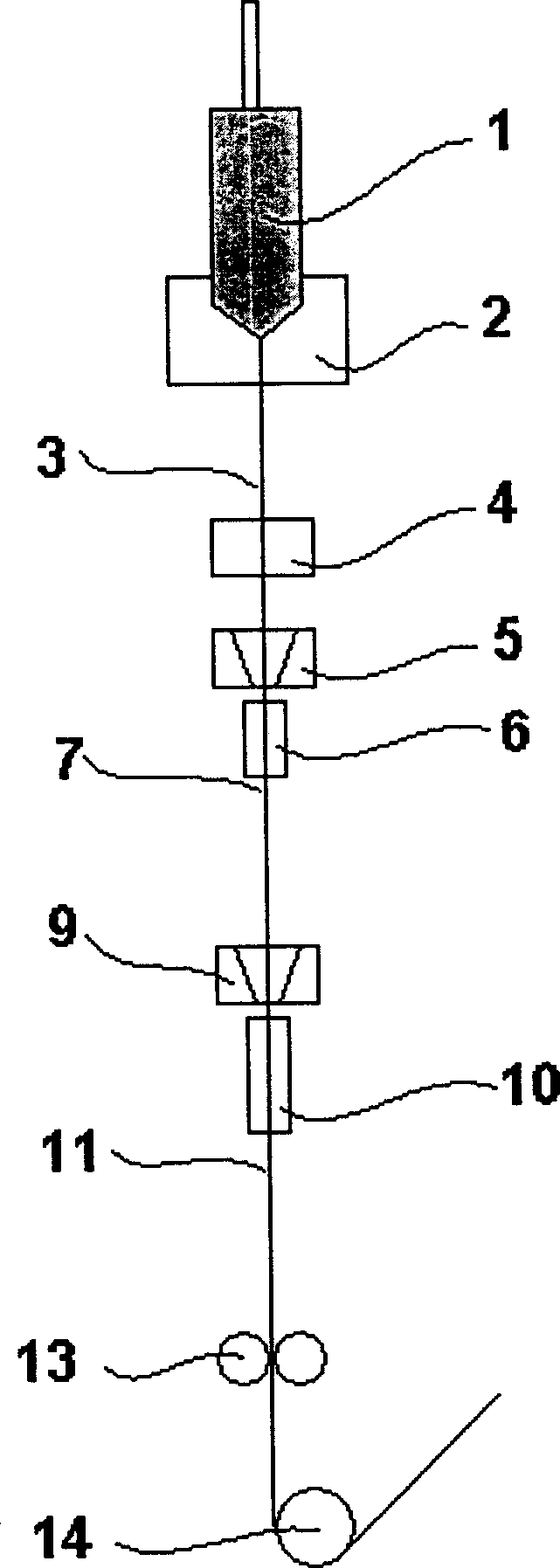
[0027] When the drawing speed reaches 1200m / min, adjust the gas flow and temperature of cooling pipe A (see Table 1), and open cooling pipe B at the same time. The temperature of the cooling water in the cooling pipe B is 20°C. Nitrogen gas is passed into the cooling pipe from the top of the cooling pipe to forcibly cool the optical fiber. The flow rate of the nitrogen gas is 2.5 L / min. Such as Figure 5 shown.

[0028] The optical fiber coating drawn by this method has no deformation a...

Embodiment 2

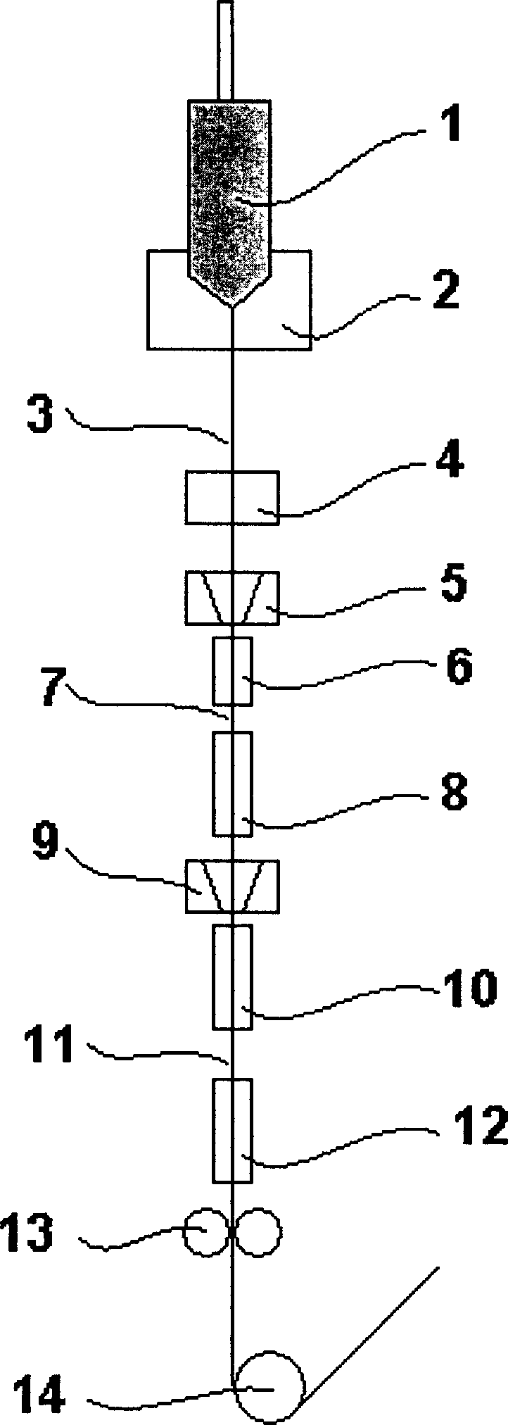
[0031] The optical fiber drawing process is the same as in Example 1. When the drawing speed reaches 1500m / min, the gas ratio, flow rate and temperature of cooling pipe A are shown in Table 2. The temperature of cooling water in cooling pipe B is 15°C. The fiber is forcedly cooled by helium gas flowing through the tube, and the flow rate of the helium gas is 5 L / min. Such as Figure 6 shown.


PUM

PropertyMeasurementUnit
lengthaaaaaaaaaa
diameteraaaaaaaaaa

Abstract

A process for drawing optical fibre at high speed features that a cooling unit is additionally used between the outlet of the UV solidifying furnace for internal coated layer and the coater of external coated layer, and a cooling unit is additionally used between the outlet of the UV solidifying furnace for external coated layer and the kneading unit respectively for forced cooling to coated optical fibre in order to fully solidify the resin, so protecting optical fibre.

Description

technical field [0001] The invention relates to a method for drawing an optical fiber at high speed, wherein the coating of the optical fiber is not deformed and damaged under the high-speed drawing condition. Background technique [0002] In order to mass-produce optical fibers at low cost, the use of larger-sized optical fiber preforms and higher drawing speeds has become the goal pursued by optical fiber manufacturers. However, as the drawing speed increases, the optical fiber is more susceptible to external influences during the drawing process, especially the coating of the optical fiber is easily damaged at a high drawing speed. [0003] Traditional fiber drawing process and main devices such as figure 1 shown. The drawing device includes a wire drawing furnace 2, and the preform 1 is fed into the wire drawing furnace 2 at a certain rate under the action of a feeding mechanism (not shown). The preform 1 is heated to 2000-2400°C in the drawi...

Claims


Application Information

Patent Timeline
Patent Type & Authority Applications(China)
IPC IPC(8): C03B37/025C03C25/10
CPCY02P40/57
Inventor 谢康朱坤黄代勇蒋晓强
Owner SHANTOU HIGH TECH ZONE AOXING OPTICAL COMM EQUIP
Why Eureka
Try Eureka