
Real time monitoring forecasting device of coal rock dynamic disaster and forecasting method

A technology for real-time monitoring and dynamic disasters, applied in measuring devices, geophysical measurements, material analysis through electromagnetic means, etc., can solve the problem that the power supply and transmission channel of the safety monitoring system cannot be shared, and the resources of the KJ coal mine safety monitoring system cannot be shared. Realize continuous and uninterrupted monitoring and forecasting, and achieve the effect of improving forecasting reliability, small size, real-time continuous monitoring and forecasting

Active Publication Date: 2005-05-25
CHINA UNIV OF MINING & TECH
View PDF7 Cites 45 Cited by
  • Summary
  • Abstract
  • Description
  • Claims
  • Application Information

AI Technical Summary

Problems solved by technology

Invention patent "Method and device for predicting gas-bearing coal and rock concrete disaster" (ZL98111185.8) through non-contact monitoring of the electromagnetic radiation signal generated when the loaded coal rock mass deforms and ruptures and its short-term (several minutes) change law, the coal mine can be predicted. The danger of coal-rock dynamic disasters such as gas outburst and rock burst reflects the instantaneous state of a certain stage in the evolution process of coal-rock dynamic disasters. It has not realized continuous and uninterrupted monitoring and forecasting, and cannot share the KJ coal mine. Resources for Safety Monitoring Systems
[0009] The utility model patent "Electromagnetic Radiation Monitoring Device for Coal and Rock Dynamic Disasters" (Patent No. ZL 01 272808.X) can perform continuous monitoring with an external power supply, but it cannot be connected with the KJ series coal mine safety monitoring system and cannot share the safety monitoring system separate power supply and transmission channel, separate wiring and separate power supply are required to realize remote monitoring, and the forecasting function is weak
[0010] There are no mature technologies and devices for real-time monitoring and forecasting of small-scale coal-rock concrete disasters (such as coal and gas outbursts, dam foundation instability, landslides and rock bursts, etc.) by using electromagnetic radiation methods and their hazards.

Method used


Image

  • Real time monitoring forecasting device of coal rock dynamic disaster and forecasting method
  • Real time monitoring forecasting device of coal rock dynamic disaster and forecasting method
  • Real time monitoring forecasting device of coal rock dynamic disaster and forecasting method

Examples


Embodiment Construction

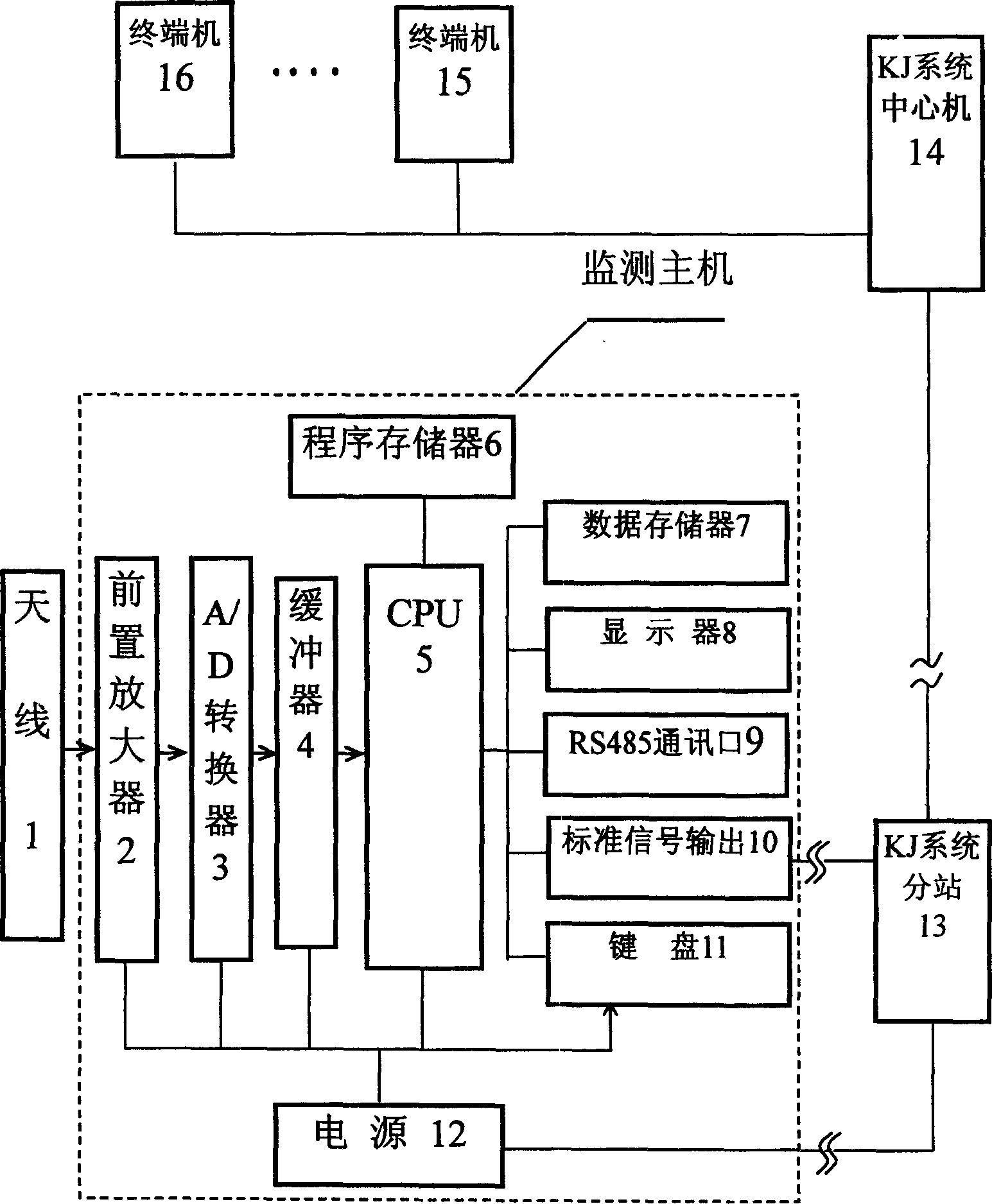
[0041] The receiver of the present invention is composed of the following parts: central processing unit CPU5, preamplifier 2, A / D converter 3, clock circuit, standard signal output circuit 10, display 8 and so on. They will be explained separately below.

[0042] 1) Central processing unit

[0043] The central processing unit of the present invention selects the 80C196KB single-chip microcomputer of MCS-96 series for use, and the clock frequency selects 12MHz for use. Considering that this system is mainly test data and does not perform complex data processing, the 27C128 with 16K bytes of program memory can meet the requirements.

[0044] According to the design requirements, the system can not only transmit the test data to the sub-station of the monitoring system through the 485 interface or the standard output interface at any time, but also store the test data for later transmission to the host. Therefore, the capacity of random access memory in the system is required ...


PUM


Abstract

The coal petrographic dynamic calamity real-time monitoring prediction device and prediction method relate to a technique for continuously monitoring coal petrographic concrete deformation break'up electromagnetic radiation information and its device. Said device includes preamplifier, A / D converter, buffer, CPU, program memory, data memory, display, RS485 communication interface, standard signal output circuit and keyboard formed monitoring main machine, also includes antenna, power supply, KJ system branch station and KJ system center machine. Said invention also provides its real-time monitoring prediction method.

Description

technical field [0001] The invention relates to a technique and a device for real-time monitoring of coal rock concrete deformation and cracking process or prediction and forecasting of coal rock concrete dynamic disasters through continuous and uninterrupted monitoring of coal rock concrete deformation and cracking electromagnetic radiation (EME) information. The invention belongs to the technical field of mine safety monitoring and forecasting equipment. Background technique [0002] The range of coal-rock dynamic disasters is very wide, involving many engineering fields and natural disasters. Under mine conditions, there are coal and gas outbursts, rock and gas outbursts, mine rock burst, roof subsidence, and slope slips, etc.; on the ground, there are mountain slips, earthquakes, dam foundation instability, and rock-concrete building instability. collapse etc. The hazards of coal-rock dynamic disasters are enormous, not only bringing a larg...

Claims


Application Information

Patent Timeline
IPC IPC(8): G01N27/00G01V9/00
Inventor 王恩元何学秋周广来刘贞堂
Owner CHINA UNIV OF MINING & TECH
Learn More