Defining and displaying device of fiber machine

A display device and mechanical technology, which is applied in the directions of weaving auxiliary equipment, looms, warping machines, etc., to achieve the effect of simplifying the structure, reducing the processing and reducing the cost.

Inactive Publication Date: 2005-06-01
TSUDAKOMA KOGYO KK
View PDF0 Cites 5 Cited by
  • Summary
  • Abstract
  • Description
  • Claims
  • Application Information

AI Technical Summary

Problems solved by technology

[0007] However, in the above-mentioned prior art, it is unavoidable that the textile machine will stop f

Method used


Image

  • Defining and displaying device of fiber machine
  • Defining and displaying device of fiber machine
  • Defining and displaying device of fiber machine

Examples


Embodiment Construction

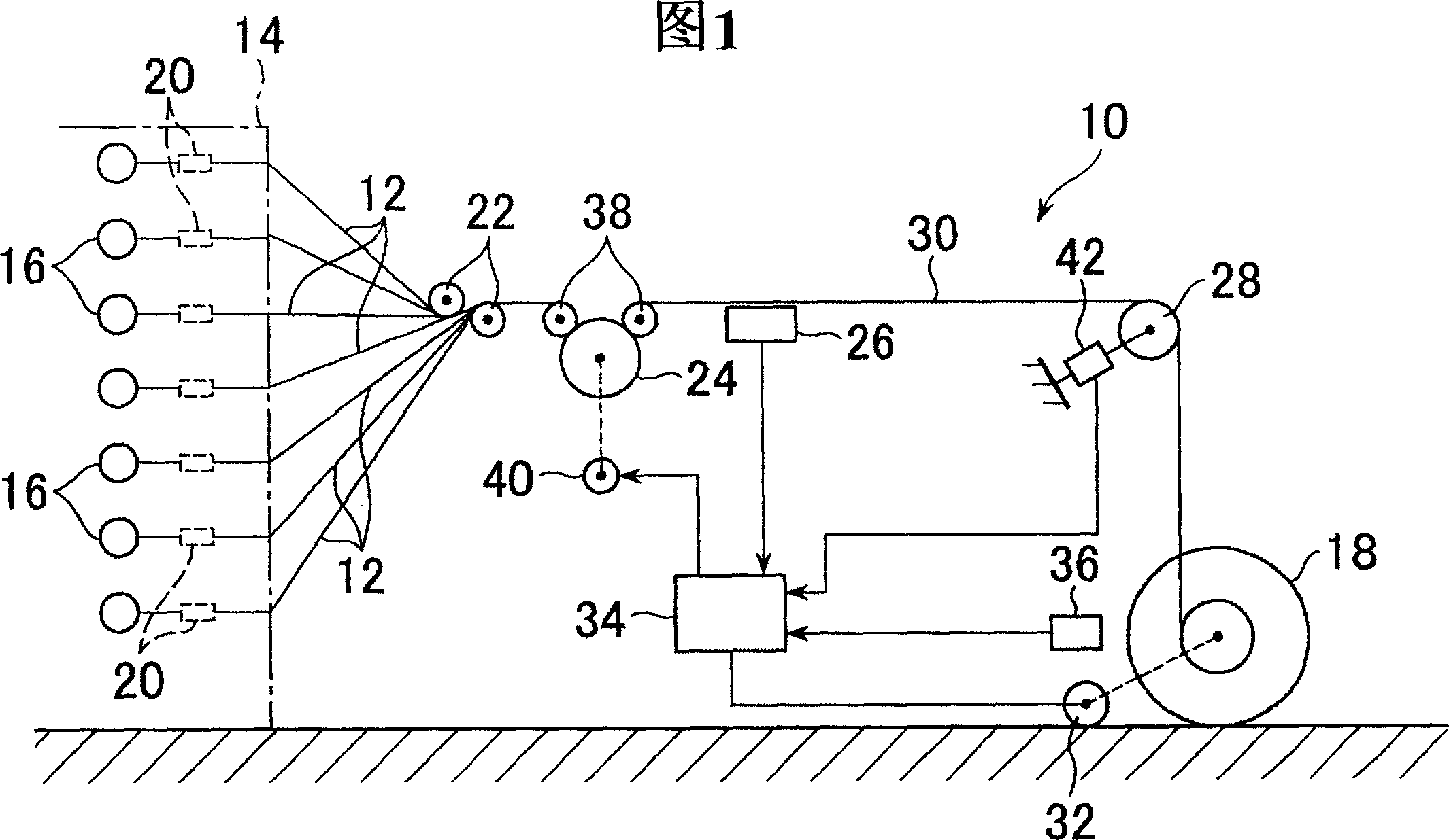
[0024] Referring to Fig. 1, a textile machine 10 serves as a warp winding device. The plurality of yarn feeders 16 around which the warp yarn 12 is respectively wound around the creel 14 are arranged in parallel in a plurality of rows along three-dimensional directions such as the up-down direction, the left-right direction, and the front-rear direction. The warp winding device 10 is a winding device for winding the warp yarns 12 drawn out from the respective yarn feeders 16 placed on the roving creel 14 in a sheet form to a winding shaft 18 .

[0025] These warp yarns 12 wound on the yarn feeder 16 are drawn out from the roving creel 14 through the tensioner 20 provided by each roving frame 1 yarn feeder, and then passed through a pair of guide rollers 22 to gather into a sheet. shape, also through take-up roller 24, warp yarn sensor 26 and tension roller 28 are drawn out simultaneously, thereby these many warp yarns 12 are juxtaposed into sheet shape and are wound on the win...


PUM


Abstract

The object of the present invention is to reduce costs related to spare parts which a user has so as to deal with part troubles. Besides an ordinary setter comprising a first indicator and a first input unit, the setting display device for a textile machine is also equipped with an emergency setter furnished with a second indicator and a second input unit having a restricted display amount of information per screen in comparison with the ordinary setter. The emergency setter is used when the ordinary setter malfunctions. The emergency setter enables input information by the second input unit to be outputted to a controller. The controller pre-stores a program for dealing with the emergency setter, which renews and sends display information that is display information related to input demand information for display item information, data information, and an operator, and is displayed by a string or a numerical value according to input information from the emergency setter.

Description

technical field [0001] The present invention relates to a device for setting and displaying information used in textile machines such as warp yarn preparation machines, weft yarn preparation machines, and looms. Background technique [0002] In order to make the textile machine work correctly, the operator completes operations such as setting and display of operation control information, setting and display of operation (quality) information, and machine operation of counter reset. Such work is performed by using a setter. [0003] A setting device connected to a controller (PLC) is described in Patent Document 1 as one of such setting devices. [0004] Patent Document 1: Patent No. 2870384 [0005] In the prior art described above, a touch panel type setting device is used that displays images, characters, etc. on the screen of a monitor, and the operator touches a predetermined part of the screen to perform switching of the display screen and input of a set value, etc. ...

Claims


Application Information

Patent Timeline
IPC IPC(8): D03D51/00B65H63/00D02H5/00D02H7/00D02H13/00D02H13/02D03J1/00
CPCD01H13/14D02H13/02D03D51/06D03D51/28D03J1/005
Inventor 西村勋
Owner TSUDAKOMA KOGYO KK
Why Eureka
Try Eureka