
Fiber-optic based cavity ring-down spectroscopy apparatus

An optical fiber ring, optical fiber technology, applied in the field of absorption spectroscopy, can solve problems such as high cost and component misalignment

Inactive Publication Date: 2005-06-08
THE TRUSTEES FOR PRINCETON UNIV
View PDF1 Cites 19 Cited by
  • Summary
  • Abstract
  • Description
  • Claims
  • Application Information

AI Technical Summary

Problems solved by technology

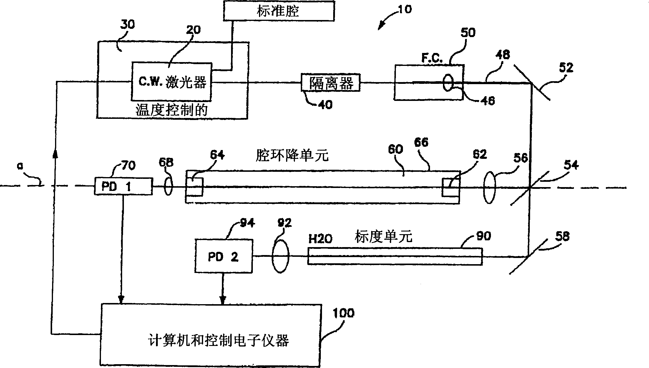
[0018] Compared with other spectroscopy methods, although cavity ring-down spectroscopy is simpler and less expensive to implement, it is still expensive, and the cost of each cavity ring-down spectroscopy system is on the order of thousands of dollars.
In addition, the optical components of traditional CRDS equipment are prone to misalignment between components during manufacture and use

Method used


Image

  • Fiber-optic based cavity ring-down spectroscopy apparatus
  • Fiber-optic based cavity ring-down spectroscopy apparatus
  • Fiber-optic based cavity ring-down spectroscopy apparatus

Examples


Embodiment Construction

[0044] Figure 4 Shown is an optical fiber based loop-down device 400 according to a first embodiment of the present invention, by means of which a tracer substance or analyte in a gas or liquid can be detected. Figure 4 In the embodiment, the device 400 includes a resonant fiber optic loop 408 including a fiber optic cable 402 and sensors 500 distributed along the length of the fiber optic cable 402 (described in detail below). The length of the fiber resonant ring 408 can be easily adjusted for different acquisition situations, such as surrounding detection or passing through multiple segments of physical configuration. Although multiple sensors 500 are shown distributed along the length of fiber optic loop 408, only one sensor 500 may be used by the present invention if desired. The distribution of more than one sensor 500 makes it possible to sample the tracer substance at all different points of the installation location. The invention can also be practiced by combinin...


PUM

PropertyMeasurementUnit
radiusaaaaaaaaaa

Abstract

An apparatus for detection and measurement of trace species in a gas or liquid sample. A ring down cell formed from a fiber optic ring is exposed to the sample gas or liquid. A coherent source emits radiation into the fiber optic ring, which in turn is received at an output thereof. The fiber optic ring has a portion thereof, between the input and output, exposed to the sample gas or sample liquid. A processor is coupled to the receiver and determines the level of trace species in the gas or liquid sample based on the rate of decay of the radiation within the fiber optic ring.

Description

technical field [0001] The present invention relates generally to absorption spectroscopy and, in particular, to how to use fiber resonators in ring-down cavity spectroscopy. Background technique [0002] Referring now to the drawings, wherein like reference numerals represent like elements throughout, figure 1 The electromagnetic spectrum on a logarithmic scale is illustrated. The science of spectroscopy studies the spectrum. Compared to disciplines dealing with other parts of the spectrum, optics is particularly concerned with visible and near-visible light - a very narrow part of the available spectrum with wavelengths from about 1 mm to about 1 nm. Near visible light includes colors redder than red (infrared) and more purple than violet (ultraviolet). This range extends far on both sides of visible light, and they can still be handled by most lenses and mirrors made of common materials. The wavelength dependence of the optical properties of these materials often has ...

Claims


Application Information

Patent Timeline
Patent Type & Authority Applications(China)
IPC IPC(8): G01N21/27G01J3/42G01N21/39G01N21/55G01N21/77
CPCG01J3/42G01N21/39G01N21/552G01N2021/391G01N2021/7789
Inventor 凯文·K·莱曼彼得·B·塔尔萨保罗·拉比诺维茨
Owner THE TRUSTEES FOR PRINCETON UNIV
Learn More