Pressure release valve in electric water heater

An electric water heater and pressure relief valve technology, which is applied to safety valves, balance valves, valve devices, etc., can solve problems such as the inability to guarantee the uniformity of the internal pressure relief pressure, the difficulty in assembling and disassembling valve components, and the inability to adjust the balance pressure. Easy replacement, easy assembly and disassembly, and consistent results

Inactive Publication Date: 2005-06-15
胡龙
View PDF0 Cites 11 Cited by
  • Summary
  • Abstract
  • Description
  • Claims
  • Application Information

AI Technical Summary

Problems solved by technology

[0003] The present invention aims to solve the problems of difficult assembly and disassembly of the valve components of the existing electric water heater pressure relief valve due to the above-mentioned structural defects, difficult maintenance of the valve itself, inability to adjust the balance pressure, and inability to ensure the unifor

Method used


Image

  • Pressure release valve in electric water heater
  • Pressure release valve in electric water heater
  • Pressure release valve in electric water heater

Examples


Embodiment Construction

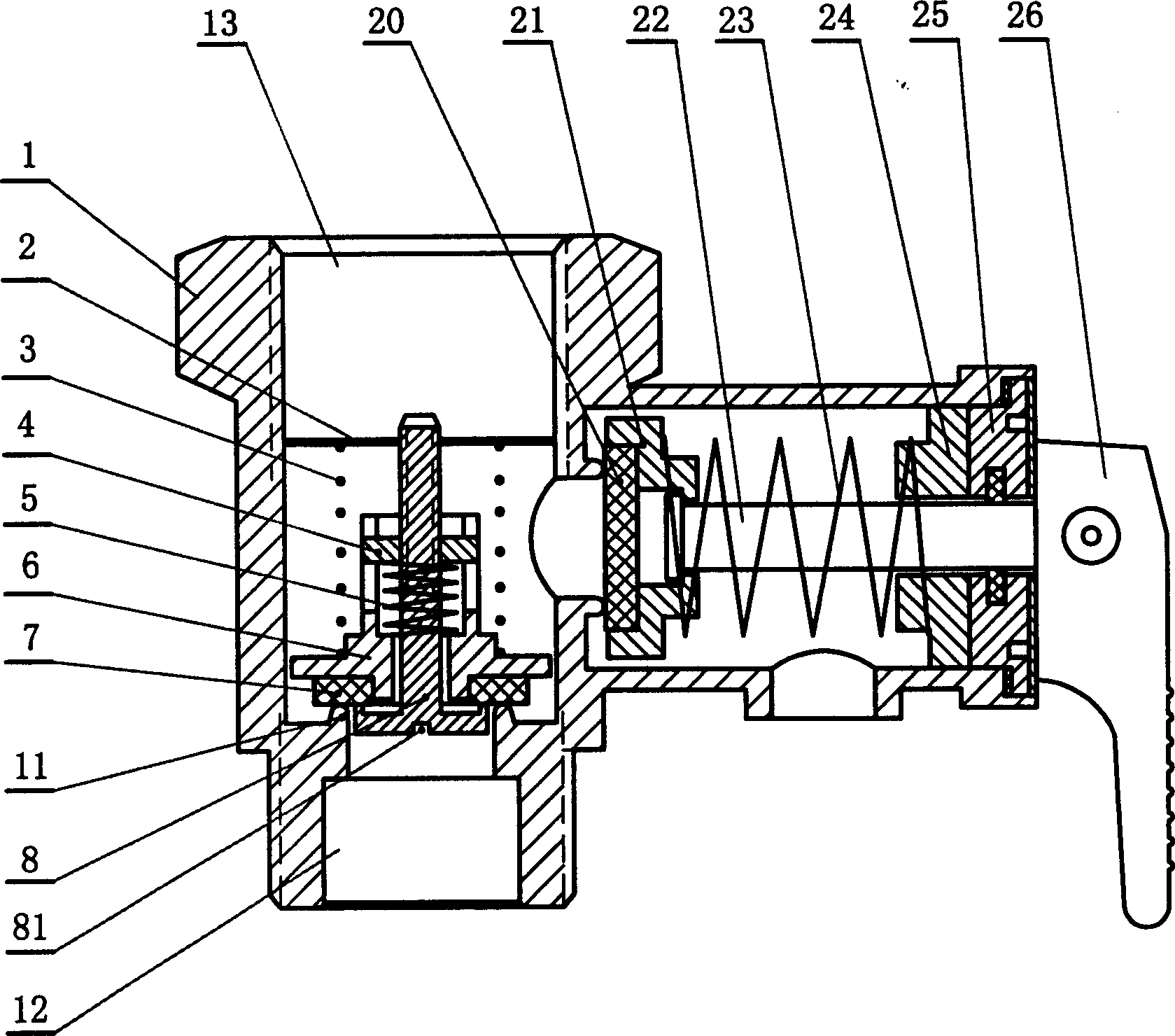
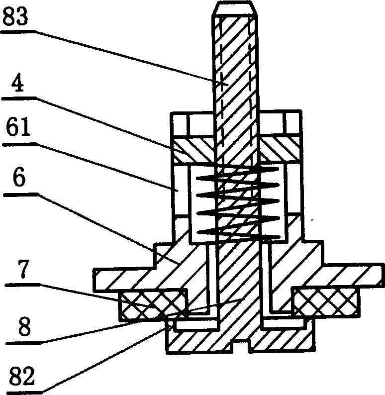
[0010] Electric water heater pressure relief valve, the water inlet channel of the valve body 1 is provided with an inner pressure relief valve seat 6 and a retaining ring 2, a spring I3 is arranged between the inner pressure relief valve seat and the retaining ring, and the inner pressure relief valve seat is embedded with The sealing gasket 7 corresponds to the water inlet valve seat 11, the inner pressure relief valve seat is pierced with an inner pressure relief valve core 8, and the outer pressure relief channel of the valve body 1 is provided with an outer pressure relief valve core 21 on which a seal Gasket 20, the outer pressure relief valve core 21 is connected with a pull rod 22, and the rear part is covered with an adjusting gland 24 and a female 25, which are built in and positioned at the rear end of the outer leak chamber of the valve body. The pull rod is covered with a spring III23, and the pull rod 22 The outer end is connected with a handle 26, and the upper p...


PUM


Abstract

The invention relates to a relief valve for electric water heater. It includes valve body, internal relief valve seat, relainer ring, spring, internal relief valve core, external relief valve core, sealing washer, drawbar, regulating pressure cover regulating nut and screw rod, etc. Said invention also provides their connection mode and the concrete structure of the above-mentioned every component.

Description

technical field [0001] The present invention pertains to spring loaded safety valves. Background technique [0002] The safety valve on the electric water heater consists of two pressure relief parts, the internal pressure relief and the external pressure relief. The external pressure release can ensure that the pressure of the inner tank of the electric water heater is not higher than the safe setting value, and the internal pressure release can adjust the uniformity of the inner tank pressure of the water inlet pressure. When the inner tank pressure exceeds a certain value, a part of the inner tank will Water returns to the water pipe through the internal pressure relief channel, and when the water is cut off, it can ensure that the water in the inner tank remains at a certain amount, so that the electric water heater will not be empty due to water shortage. The pressure relief spool (such as image 3 (shown) is provided with a diameter-reducing groove 30, and the valve c...

Claims


Application Information

Patent Timeline
IPC IPC(8): F16K17/04
Inventor 胡龙
Owner 胡龙
Why Eureka
Try Eureka