Pipe fitting type examination well

A technology for inspection wells and pipe fittings, applied in the field of inspection wells, can solve problems such as long construction period, shrubs and weeds, and poor water flow, and achieve the effects of shortening construction period, high degree of industrialization, and tight interface

Active Publication Date: 2005-06-22
JIANGSU HIPPO PLASTICS
View PDF0 Cites 16 Cited by
  • Summary
  • Abstract
  • Description
  • Claims
  • Application Information

AI Technical Summary

Problems solved by technology

At present, large-scale underground pipelines are inspection wells such as sewers, industrial and mining sewage discharge pipelines, underground communications, cable placement pipelines, etc., especially for inspection wells in sewer pipelines. Build a well body to the ground, and then cover it with a well cover, and open an opening on the side of the well body for pipeline connection; the existing problems are that the construction period is long, it is easy to produce shrubs and weeds, it is inconvenient to dredge, and the water flow is not smooth. Moreover, there is serious leakage at the connection between the pipeline and the well body (especially the connection between the traditional cement well and the plastic pipe), which will lead to secondary pollution of the surrounding environment
There are also prefabricated cement wells. Although it can shorten the pipeline construction period, it still has the above-mentioned other problems. Moreover, when it is in the pipeline and connected with the pipeline, because its height cannot be adjusted, the well cover on the cover is generally not level with the ground

Method used


Image

  • Pipe fitting type examination well

Examples


specific Embodiment approach

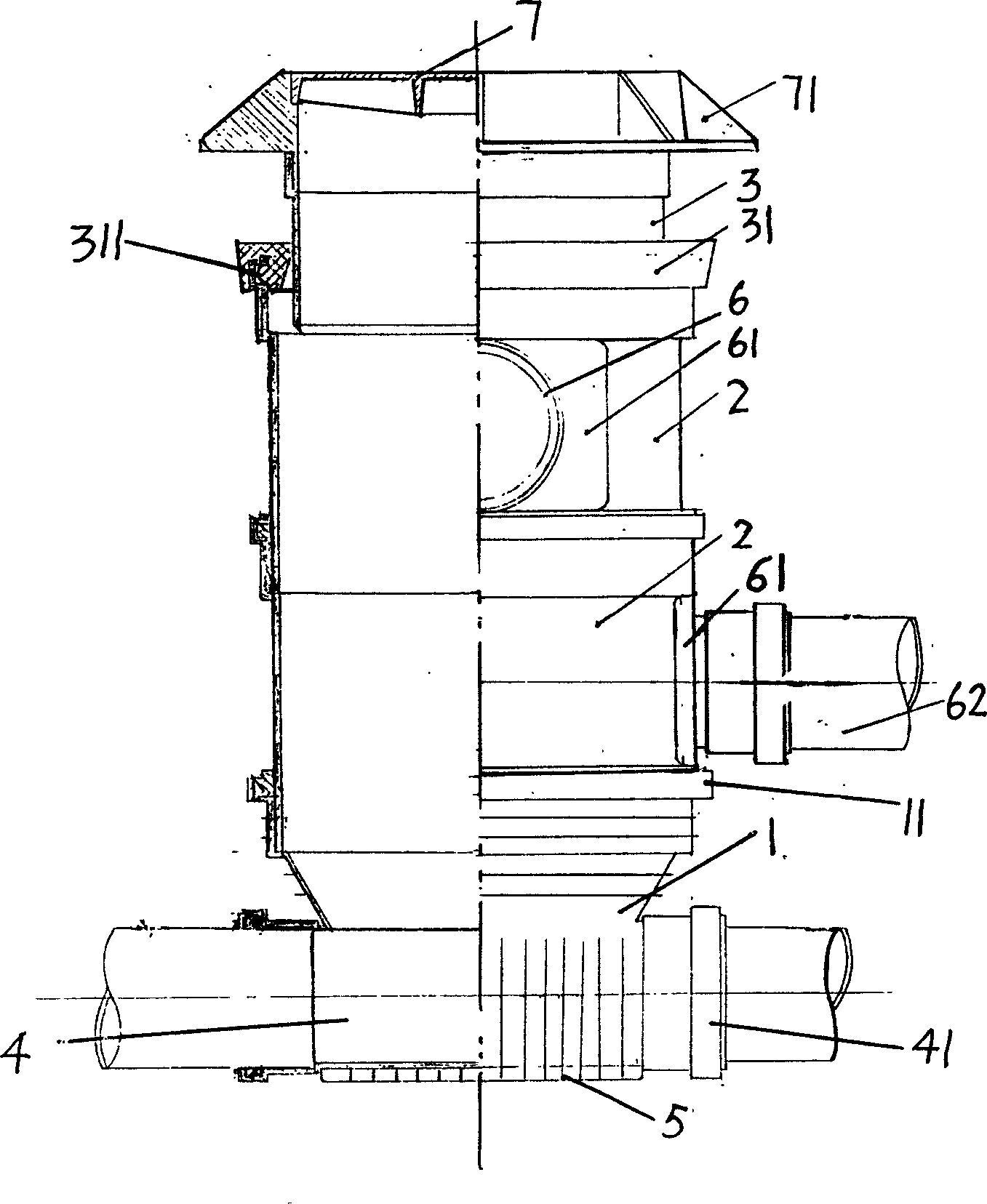
[0016] The inner hollow well body 1 is connected with a main flow pipe 4 , and the bottom of the main flow pipe 4 protrudes outward to form a collection chamber 5 . A well body socket 11 is arranged above the well body 1, a connecting pipe 2 is arranged close to the inner side wall of the well body socket 11, a telescopic tube 3 is arranged close to the inner side wall of the connecting pipe 2, and the telescopic pipe 3 is covered with a telescopic tube The ferrule 31 has an annular slot 311 , and the upper edge of the connecting pipe 2 below the telescopic tube 3 is embedded in the slot 311 . The main channel pipe 4 is located at the bottom of the well body 1, and has two main channel nozzles 41 communicating with the outside world and the inner cavity of the well body 1. The side wall of the connecting pipe 2 above the main channel pipe 4 is provided with two different heights. Branch port 6. The side wall of the connecting pipe 2 at the branch pipe opening 6 is provided wi...


PUM


Abstract

Disclosed is a pipe fitting type examination well, which comprises a hollow well member, which is connected with a main flow passage, a well member pipe socket is arranged above the well member, a coupling pipe is arranged on the internal walls near the well member pipe socket, a telescopic pipe is arranged on the medial wall of the coupling pipe, the main flow passage tube is on the bottom of the well member. The invention can realize easy pipe line construction.

Description

technical field [0001] The invention relates to the field of pipeline fittings, in particular to inspection wells in large pipeline systems. Background technique [0002] Inspection wells in underground pipeline systems are also called pipeline wells and inspection wells. At present, large-scale underground pipelines are inspection wells such as sewers, industrial and mining sewage discharge pipelines, underground communications, cable placement pipelines, etc., especially for inspection wells in sewer pipelines. Build a well body to the ground, and then cover it with a well cover, and open an opening on the side of the well body for pipeline connection; the existing problems are that the construction period is long, it is easy to produce shrubs and weeds, it is inconvenient to dredge, and the water flow is not smooth. Moreover, there is serious leakage at the connection between the pipeline and the well body (especially the connection between the traditional cement well an...

Claims


Application Information

Patent Timeline
Patent Type & Authority Applications(China)
IPC IPC(8): E02D29/12
Inventor 周佰兴
Owner JIANGSU HIPPO PLASTICS
Why Eureka
Try Eureka