Unitary piping inspection well

An integrated, inspection well technology, applied in the field of inspection wells, can solve the problems of long construction period, secondary pollution of the surrounding environment, poor water flow, etc., and achieve the effect of high degree of industrialization, shortened construction period, and tight interface

Inactive Publication Date: 2004-12-08
周佰兴
View PDF0 Cites 14 Cited by
  • Summary
  • Abstract
  • Description
  • Claims
  • Application Information

AI Technical Summary

Problems solved by technology

At present, large-scale underground pipelines are inspection wells such as sewers, industrial and mining sewage discharge pipelines, underground communications, cable placement pipelines, etc., especially for inspection wells in sewer pipelines. Build a well body to the ground, and then cover it with a well cover, and open an opening on the side of the well body for pipeline connection; the existing problems are that the construction period is long, it is easy to produce shrubs and weeds, it is inconvenient to dredge, and the water flow is not smooth. Moreov

Method used


Image

  • Unitary piping inspection well
  • Unitary piping inspection well
  • Unitary piping inspection well

Examples


Embodiment 1

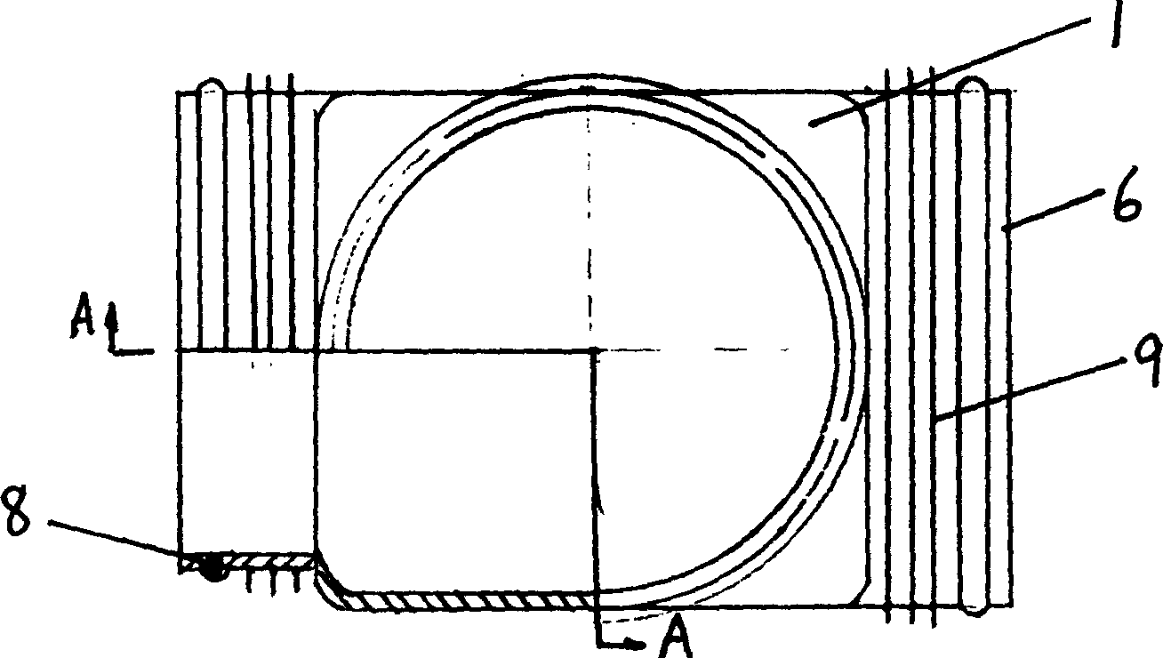
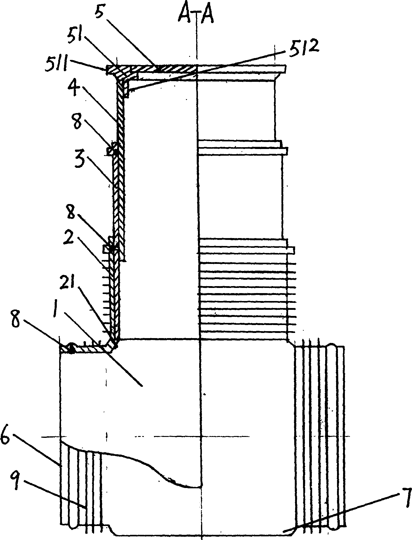
[0023] Embodiment 1: The corresponding two sides of the cuboid-shaped well body 1 are connected and communicated with a main pipeline connection port 6, the bottom of the inner cavity of the well body 1 is a collection part 7, and the upper end of the well body 1 is connected and communicated with a well body socket 2 , the inner wall of the well body socket 2 is close to the inner side wall of the well body 1 to form a ring of bosses 21 that protrude outward in the direction of the center line. The pipe 4 is close to the inner side wall of the connecting pipe 3, and the upper end of the telescopic pipe 4 is fixedly connected with the connecting ring 512 at the lower end of the manhole cover seat 51. A sealing ring 8 is provided on the connecting pipe 3 , the upper port of the well body socket 2 and the inner side wall of the port of the main pipeline connection port 6 away from the well body 1 . A reinforcing rib 9 is provided on the outer side wall of the well body socket 2 ...

Embodiment 2

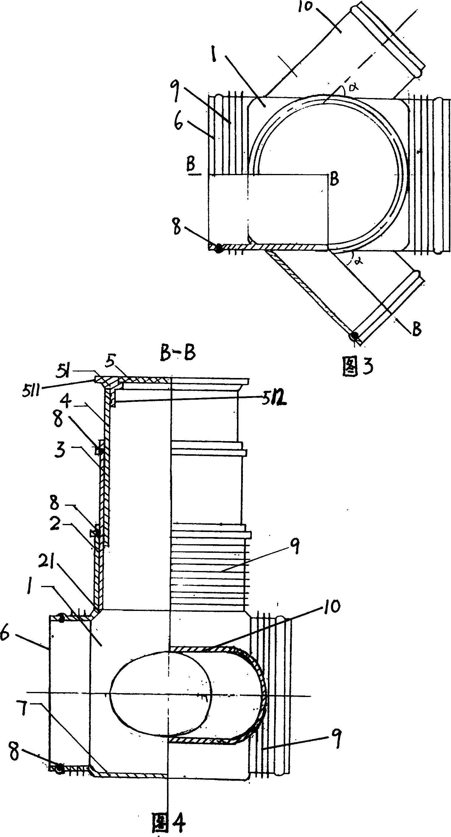
[0024] Embodiment 2: The difference from Embodiment 1 is that a pipeline connection port 10 is provided on the other two sides of the well body 1 in communication with each other, and the openings of the two pipeline connection ports face the same main pipeline connection port. A sealing ring is also provided on the inner side wall of the port of the branch pipe connecting port away from the well body. The included angle a between the center line of the branch pipe connection port 10 and the center line of the main pipe connection port 6 is 45°


PUM


Abstract

An unitary manhole has a vertical hollow shaft. An opening, at least, is arranged on its wall to connect with main channel. The shaft body, which has a telescopic structure, is above the horizontal channel body, which has an opening and a tunnel for connecting with the vertical shaft. A manhole cover is on the top of the vertical shaft. The manhole can be industrially produced, installed easily, and can meet various demands to connect tightly with channels in different angles, with short installation period and without secondary pollution.

Description

technical field [0001] The present invention relates to the field of pipeline fittings, in particular to inspection wells in large pipeline systems. Background technique [0002] Inspection wells in underground pipeline systems are also called pipeline wells and manholes. At present, inspection wells for large underground pipelines such as sewers, industrial and mining sewage discharge pipelines, underground communication, cable installation pipelines, etc., especially for manholes in sewer pipelines, most of which are used bricks (or cement) under the ground in pipeline passages. Build a well body to the ground, then cover it with a well cover, and open an opening on the side of the well body for pipeline connection; the problem is that the construction period is long, it is easy to produce shrubs and weeds, and it is difficult to dredge the water flow. In addition, there is serious leakage at the connection between the pipeline and the well body (especially the connection...

Claims


Application Information

Patent Timeline
IPC IPC(8): E02D29/12
Inventor 周佰兴
Owner 周佰兴
Why Eureka
Try Eureka