Distributed optical fiber temperature sensing and monitoring device and method for positioning dam leakage

A technology of distributed optical fiber and monitoring device, which is applied in the direction of measuring device, fluid tightness test, machine/structural component test, etc.

Inactive Publication Date: 2005-06-29
秦一涛 +2
View PDF0 Cites 37 Cited by
  • Summary
  • Abstract
  • Description
  • Claims
  • Application Information

AI Technical Summary

Problems solved by technology

[0003] The present invention will provide the field with a distributed optical fiber temperature sensor monitoring device and method for dam leakage location, so that the i

Method used


Image

  • Distributed optical fiber temperature sensing and monitoring device and method for positioning dam leakage
  • Distributed optical fiber temperature sensing and monitoring device and method for positioning dam leakage
  • Distributed optical fiber temperature sensing and monitoring device and method for positioning dam leakage

Examples


Embodiment Construction

[0048] The laying of optical cables (take the leakage monitoring of the joints around the concrete face dam as an example)

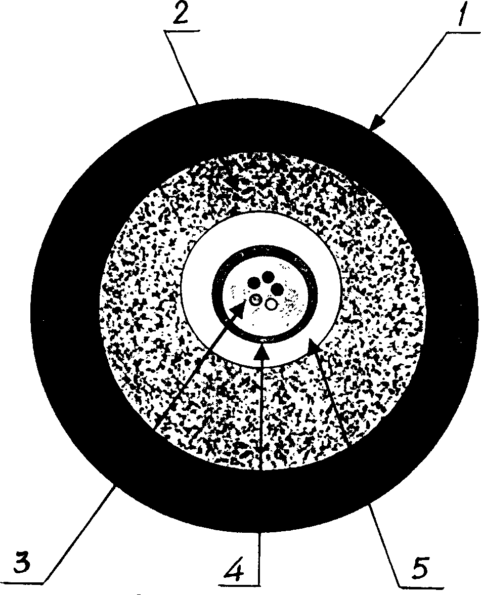
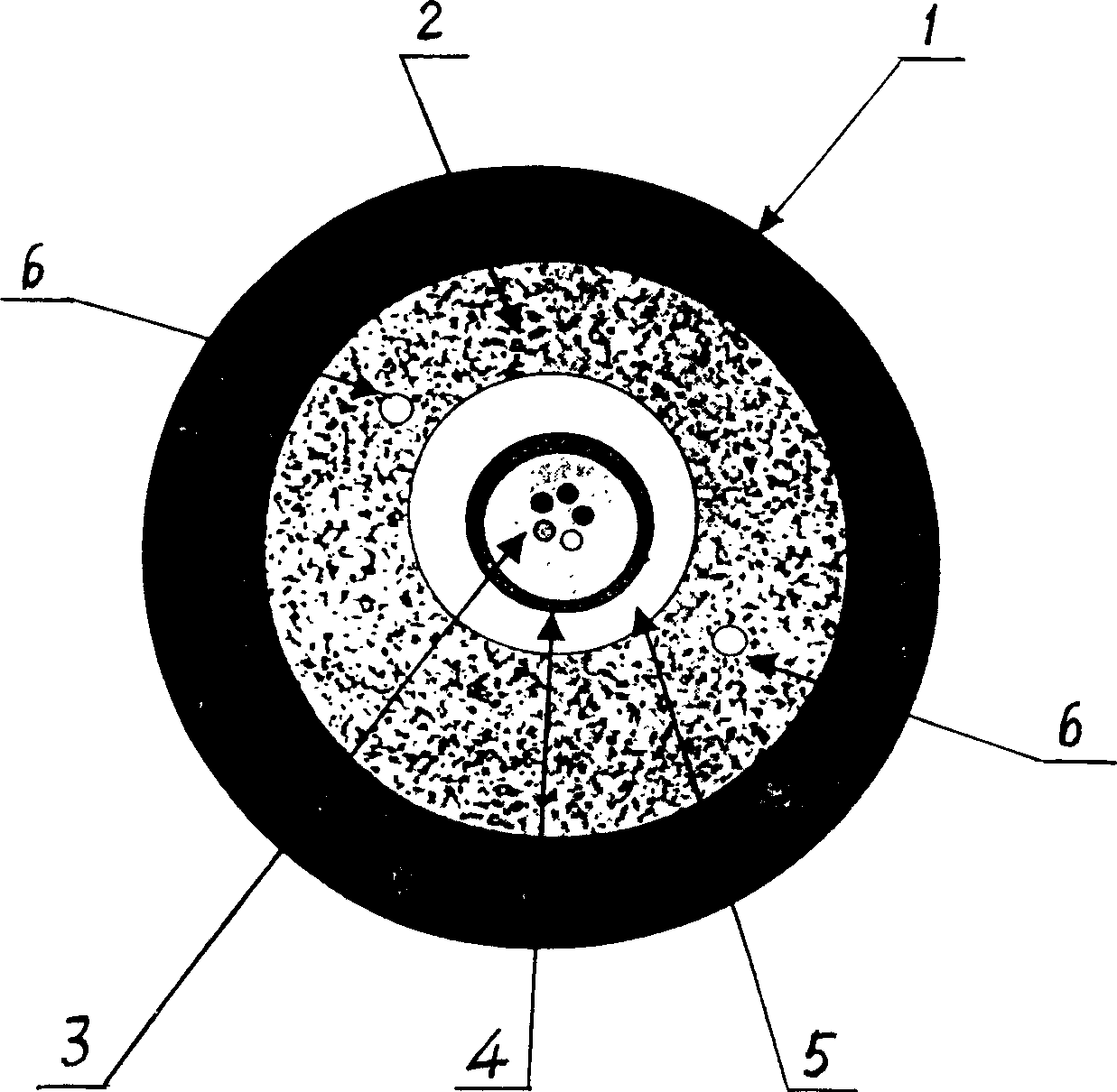
[0049] 1. Laying position: It is necessary to be able to detect the leakage in time without causing damage to the dam. The most prone to seepage of the concrete face dam is the peripheral joint, because this is generally the junction of the mountain and the dam. In the design of the dam, there are measures to waterproof the surrounding joints. However, as time goes by, the leakage of the embankment will be difficult to prevent, and the leakage will become larger and larger. In addition, there are also quality problems in the construction, and some new dams have When leakage occurs, we need to know where and how large the leakage is, so that it can be maintained in time to avoid harm. Through simulation experiments and research with experts, we lay the sensor optical cable under the cushion layer around the slab dam, measure the temperature distribution of th...


PUM


Abstract

This invention relates to water works engineering safety protection equipments field and a dam leak position distribution light fiber temperature sensor monitoring apparatus and its method. The apparatus is formed by connecting the double-coupler, wavelength-division multiplex, snow-slide diode, main amplifier, sampling even device and sum device, computer, driver, laser diode and sensor cable. The sensor cable has two structures: one is the sensor light cable core of fiber, and the outer layer of the fiber is metal center protective cover, water-tight isolation layer, aramid fiber, outer protective layer; the other is heating sensor cable with isolation heating conductor in one of its structures. íí

Description

Technical field [0001] The invention relates to the field of safety protection equipment for water conservancy projects, and is a distributed optical fiber temperature sensing monitoring device and method for dam leakage positioning. Background technique [0002] At present, the monitoring method of the leakage of the optical fiber sensor in the oil and gas pipeline has been disclosed in the patent literature. The invention discloses an intelligent online monitoring method for the leakage of the oil and gas pipeline based on the distributed optical fiber sensor. Lay one or several optical cables in parallel with the oil and gas pipelines near the oil and gas pipelines, and use optical fibers as sensors to monitor the oil and gas pipelines in real time; at both ends of the optical fiber, that is, the input and output ends of the oil and gas pipelines, a set of optical power is set for each The detection module is connected to the computer, and the computer is used to analyze and f...

Claims


Application Information

Patent Timeline
IPC IPC(8): G01M3/00
Inventor 秦一涛张弘魏德荣
Owner 秦一涛
Why Eureka
Try Eureka