Cemented carbide insert and method of making the same
A cemented carbide blade and cemented carbide technology, applied in metal processing equipment, etc., can solve problems such as increased wear resistance and loss
- Summary
- Abstract
- Description
- Claims
- Application Information
AI Technical Summary
Problems solved by technology
Method used
Image

Examples
Embodiment 1
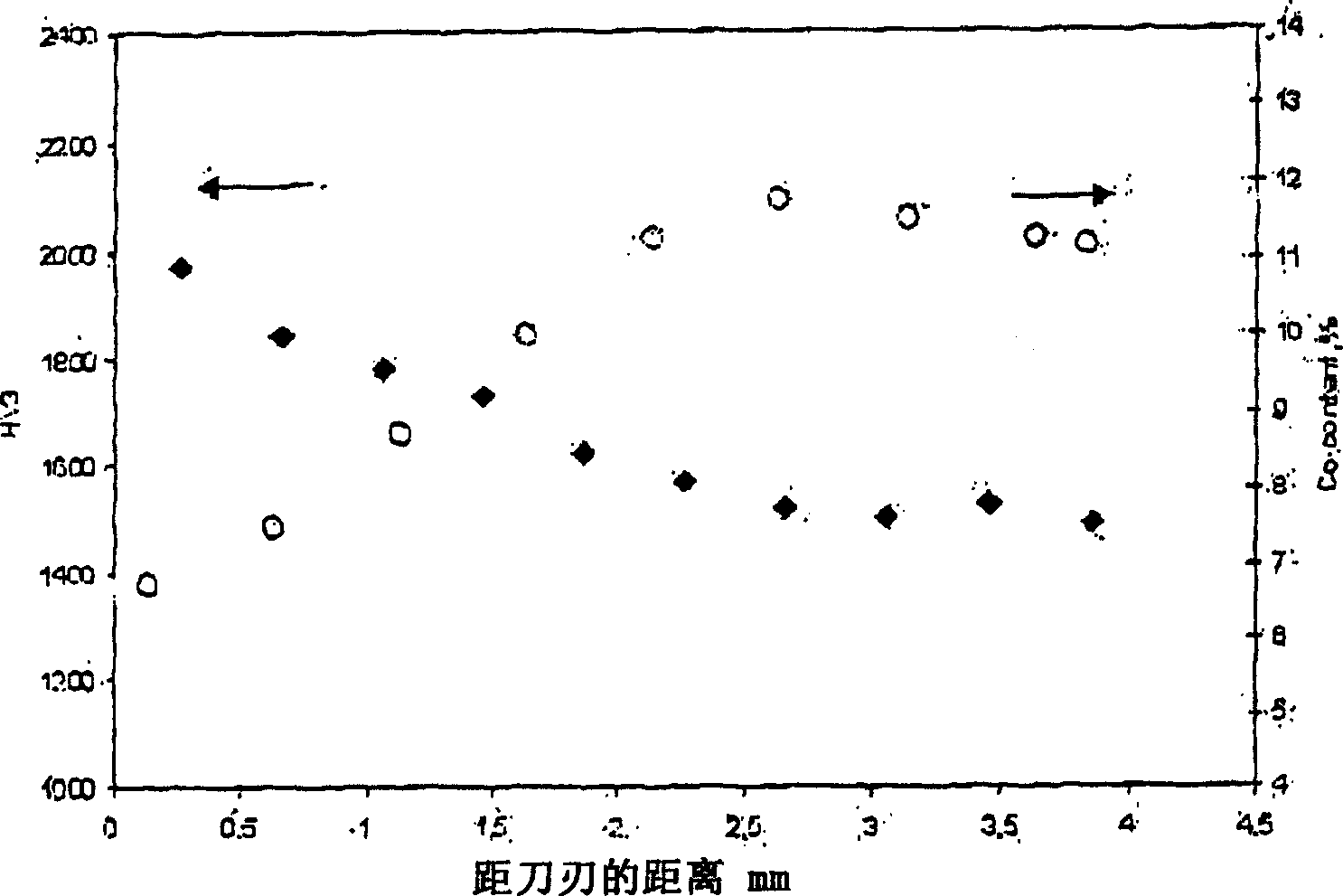
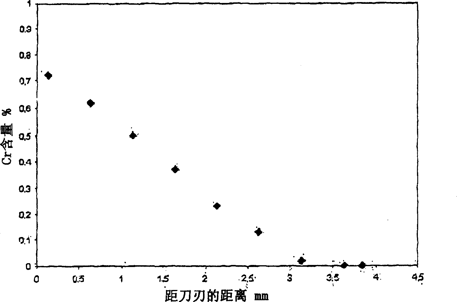
[0034] A cemented carbide compact of type B-SNGN120408 was prepared according to the following steps: a compact was pressed from a powder having a composition of 90 wt% WC and 10 wt% Co. The grains of the WC raw material were refined to an average grain size of 0.25 μm (FSSS). with Cr 3 C 2 Thin layer (0.02gCr 3 C 2 / cm 2 ) covering the rake face. Afterwards, these compacts were sintered at 1370° C. for 30 minutes, after which the outer 1 mm deep part was removed by grinding. The cross-section of the sinter-ground blank was observed. figure 1 A graph showing the relationship between hardness and cobalt content versus distance from the cutting edge. Cobalt content is lowest near the edge and increases with distance, while hardness is highest near the edge and decreases with distance. figure 2 A graph showing the relationship between chromium content and distance from the cutting edge. Chromium levels are highest near the blade edge and decrease with distance. Cobalt ...
Embodiment 2
[0036] A cemented carbide compact of type B-SNGN120408 was prepared according to the following procedure: a compact was pressed from a powder having a composition of 94 wt% WC and 6 wt% Co. The grains of the WC raw material were refined to an average grain size of 0.25 μm (FSSS). With 0.007gCr 3 C 2 / cm 2 Cover the rake face.
[0037] At 1350°C will have Cr 3 C 2 The compact of the layers was sintered for 30 minutes and a post-HIP treatment was performed at 1300° C. and 6 MPa for 30 minutes. Observe the cross-section of the sintered billet. No Cr was observed on this surface 3 C 2 . The table below shows the HV3, cobalt content, chromium content and WC grain size for this example.
[0038] HV3 1720 at 100μm from the cutting edge
[0039] HV3 1520 at 3mm from the blade
[0040] Cobalt content at 100 μm from the blade edge, wt% 4.0
[0041] Cobalt content at 3mm from the cutting edge, wt% 6.5
[0042] Chromium content at 100 μm away from the blade, wt% 0.7
[0043...
Embodiment 3
[0047] A cemented carbide compact of type B-SNGN120408 was prepared according to the following steps: a compact was pressed from a powder having a composition of 90 wt% WC and 10 wt% Co. with Cr 3 C 2 Thin layer (0.01gCr 3 C 2 / cm 2 ) covering the rake face. Afterwards, these compacts were sintered at 1370° C. for 30 minutes. The cross-section of the sintered billet was observed. No Cr was observed on this surface 3 C 2 . The table below shows the HV3, cobalt content, chromium content and WC grain size for this example.
[0048] HV3 1450 at 100μm from the blade
[0049] HV3 1280 at 3mm from the blade
[0050] Cobalt content at 100μm from the blade edge, wt% 7.5
[0051] Cobalt content at 3mm from the cutting edge, wt% 11
[0052] Chromium content at 100 μm away from the blade, wt% 0.4
[0053] Chromium content at 3mm from the blade, wt% <0.05
[0054] WC grain size at 100 μm away from the blade, μm 1.1
[0055] WC grain size at 3mm from the blade, μm 1.4
PUM
| Property | Measurement | Unit |
|---|---|---|
| thickness | aaaaa | aaaaa |
| particle size | aaaaa | aaaaa |
Abstract
Description
Claims
Application Information
 - R&D
- Intellectual Property
- Life Sciences
- Materials
- Tech Scout
- Unparalleled Data Quality
- Higher Quality Content
- 60% Fewer Hallucinations
Browse by: Latest US Patents, China's latest patents, Technical Efficacy Thesaurus, Application Domain, Technology Topic, Popular Technical Reports.
© 2025 PatSnap. All rights reserved.Legal|Privacy policy|Modern Slavery Act Transparency Statement|Sitemap|About US| Contact US: help@patsnap.com