

Coated cemented carbide insert
a technology of cemented carbide and cutting tool, which is applied in the direction of cutting tool inserts, magnetic circuit shapes/forms/construction, natural mineral layered products, etc., can solve the problems of fracturing the cutting edge, abrasion and chemical wear of the tool,
- Summary
- Abstract
- Description
- Claims
- Application Information
AI Technical Summary
Benefits of technology
Problems solved by technology
Method used
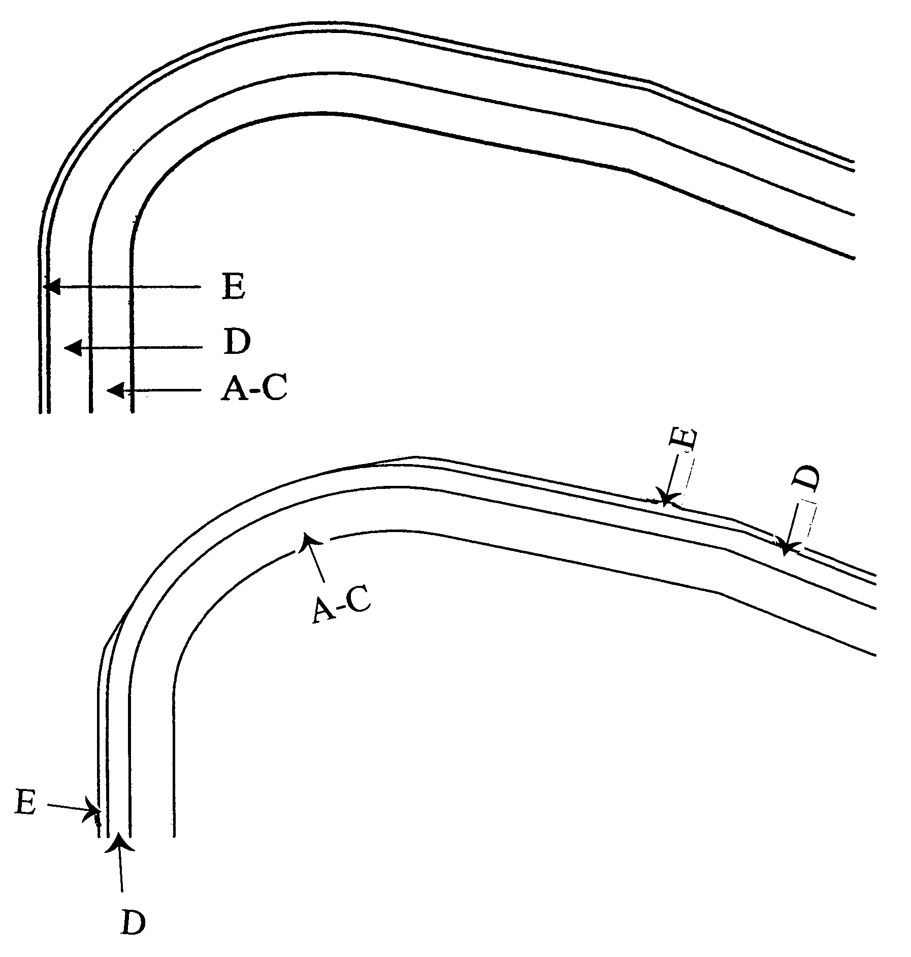
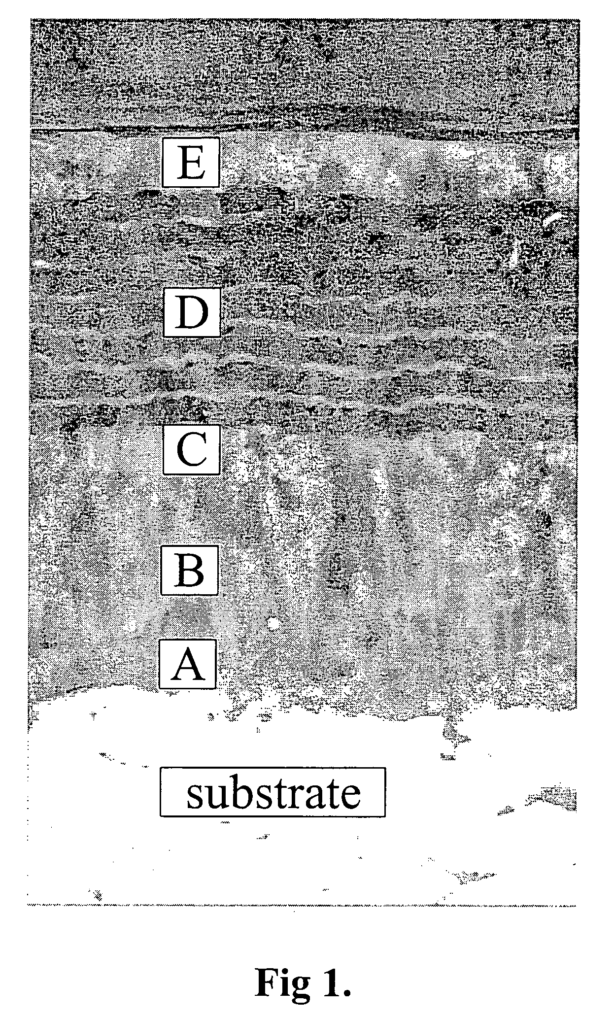
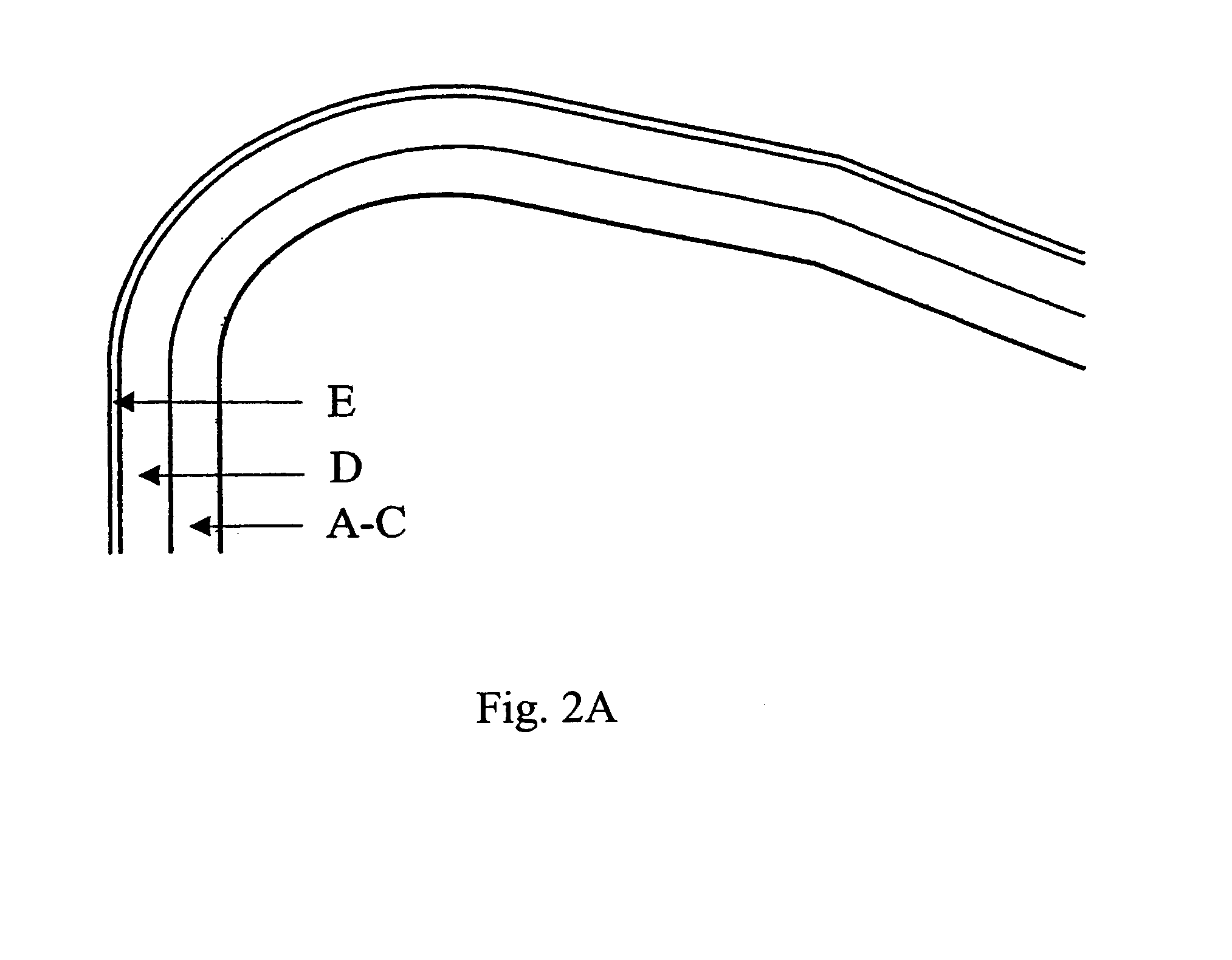
Image

Examples
example 1
[0059]Inserts from A and B were tested in a turning operation.
[0060]
Operation:Axial and facial turning in a barWork piece material:Austenitic stainless steel AISI 316LCutting Speed:225 m / minFeed rate:0.3 mm / revDepth of cut:2.0 mmInsert style:CNMG120408-MMResults:Tool life (min)Insert A: (invention)ca 10Insert B: (prior art)ca 6
[0061]Comment: Tool life criterion was maximum flank wear 0.3 mm of the cutting edge line. The wear develops irregularly due to local plastic deformation. This example shows the improvement in plastic deformation resistance.
example 2
[0062]Inserts from A and B were tested in a turning operation.
[0063]
Operation:Intermittent cutting of an assembly partWork piece material:Austenitic stainless steel, AISI316LCutting speed:160 m / minFeed rate:0.2–0.3 mm / revDepth of cut:0.5–1.5 mmInsert style:SNMG120412-MRResults:Tool life (min)Insert A: (invention)8.2Insert B: (prior art)4.2
[0064]Comment: The wear in this test was flank wear, thermal cracks, chipping. The tool-life-determining criterion is chipping i.e. edge toughness. Consequently it shows improved edge toughness in combination with maintained properties in other wear modes.
example 3
[0065]Inserts from A and B were tested in a turning operation.
[0066]
Operation:Continuous cutting in a cast ringWork piece material:Austenitic stainless steel, AISI316LCutting speed:110 m / minFeed rate:0.3 mm / revDepth of cut:3.5 mmInsert style:CNMG120412-MRResults:Tool life (min)Insert A: (invention)18.6Insert B: (prior art)12.4
[0067]Comment: The criterion in this test is working through a full item taking total time in cut 6.2 min without showing excessive flank wear or edge damage. The critical wear criteria are flank wear and plastic deformation in combination.
[0068]The insert according to the invention shows improvements in these respects.
PUM
| Property | Measurement | Unit |
|---|---|---|
| total thickness | aaaaa | aaaaa |
| total thickness | aaaaa | aaaaa |
| total thickness | aaaaa | aaaaa |
Abstract
Description
Claims
Application Information