Power converter package with enhanced thermal management

A power converter and heat transfer technology, applied in circuit thermal devices, electric solid state devices, semiconductor devices, etc., can solve the problems of increasing power loss conduction paths of power consumption components

Active Publication Date: 2005-07-13
DELTA ELECTRONICS INC
View PDF1 Cites 7 Cited by
  • Summary
  • Abstract
  • Description
  • Claims
  • Application Information

AI Technical Summary

Problems solved by technology

In addition, the power losses of power dissipating components and thei

Method used


Image

  • Power converter package with enhanced thermal management
  • Power converter package with enhanced thermal management
  • Power converter package with enhanced thermal management

Examples


Example Embodiment

[0026] Although the present invention may have various embodiments in different forms, for the sake of simplicity of description, some preferred embodiments are listed in the present invention, and detailed description and explanation are given below. However, the content disclosed in this place exemplifies the principle of the present invention, but the scope of the present invention is not limited to the following specific embodiments.

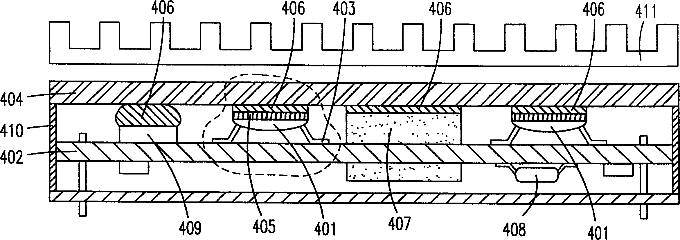
[0027] image 3 It is a cross-sectional side view of a preferred embodiment of the power conversion package of the present invention. As shown in the figure, all the electrical connections of the power converter are realized by mounting on the multilayer printed circuit board 402 so as to have a high interconnection density. A thermal diffusion element 404 is directly connected to the exposed top thermal block 405 and the magnetic element 407 of the sub-package 401 through the thermal insulator 406. The magnetic element 407 can be installed on ...


PUM


Abstract

The invention relates to a packaging technology of a power converter, in which all components are electrically connected to a multilayer circuit board. A subpackage having at least one power dissipating chip with an exposed upward facing top thermal block electrically connected to the board by a plurality of symmetrical pins. A heat spreading element is directly attached to the exposed top thermal block of the subpackage, the top surface of the planar magnetic part and other components with thermally conductive insulators. Heat dissipated by the subpackage is transferred from the exposed top thermal block to the attached heat spreader element and further to the ambient. This assembly features a compact and inexpensive power converter package with improved electrical performance and improved thermal management.

Description

(1) Technical field [0001] The present invention relates to the packaging and installation of electrical components, in particular to a package and assembly of a power converter with improved thermal management, high electrical interconnection density and small size. (2) Background technology [0002] reference figure 1 , figure 1 A schematic diagram showing the structure of the packaged electrical components in the power converter according to the prior art. Such as figure 1 As shown, the power consumption devices such as 9b, 9d and the magnetic element 9c are directly mounted on a metal substrate 6 by a conductor insulator 8 to achieve better heat conduction. The power component is electrically connected to a printed circuit board (PCB) 5a by a pin 12. The magnetic element 9c is electrically connected to the printed circuit board 5a. Other necessary components such as 9a and 9e are mounted on one or both sides of the printed circuit board 5a. This installation can be sealed ...

Claims


Application Information

Patent Timeline
IPC IPC(8): H01L23/36H01L23/42H05K1/02H05K1/14H05K3/34H05K7/20
CPCH01L23/36H01L23/42H01L2224/48247H01L2924/15311H01L2924/1532H01L2924/3011H05K1/0203H05K1/141H05K3/0061H05K3/3421H05K7/20418H05K2201/10477H01L24/48H05K7/209H01L2924/181H01L2924/00014Y10T29/4935H01L2924/00012H01L2224/45099H01L2224/45015H01L2924/207
Inventor 叶润清章进法
Owner DELTA ELECTRONICS INC
Why Eureka
Try Eureka