Display system capable of converting planar or stereo image

A technology for stereoscopic imaging and display systems, applied in optics, instruments, nonlinear optics, etc., can solve the problems of incompatibility with mass production, high production costs, and shortened object distances.

Inactive Publication Date: 2005-08-17
WINTEK CORP
View PDF2 Cites 10 Cited by
  • Summary
  • Abstract
  • Description
  • Claims
  • Application Information

AI Technical Summary

Problems solved by technology

[0004] see again image 3 , is the patent of U.S. Patent Publication No. (USPN) No. 5,969,850 announcement. Compared with the foregoing, it can be seen that one of the carrier plates 6 of the liquid crystal display 4 is removed, and the object distance d is shortened so that the viewing distance D reaches about 35 centimeters. Although it It can meet the application range of small and medium size displays, but it must carry out multiple processes such as coating, etching (etch), and alignment (rubbing) on ​​both sides of the carrier plate 6. Obviously, it is only different from the existing technology. The panel process of plating, etching, and alignment on one side of the carrier plate 6 is quite different, so its production cost is quite high, which obviously does not meet the needs of mass production

Method used


Image

  • Display system capable of converting planar or stereo image
  • Display system capable of converting planar or stereo image
  • Display system capable of converting planar or stereo image

Examples


Embodiment Construction

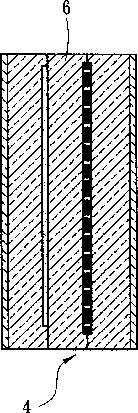
[0024] In order to have a deeper understanding and recognition of the features, purposes, and effects of the present invention, the preferred embodiments are now listed and described in conjunction with the accompanying drawings as follows:

[0025] see Figure 4 , is the structure diagram of the first embodiment, the parallax barrier 20A is arranged on the outside of the display device 30, and the parallax barrier 20A is arranged in sequence from the inside to the outside with a second polarizer 24, a second carrier plate 23, and a liquid crystal layer 25. A first polarizer 21 and a first carrier plate 22, the first carrier plate 22 and the second carrier plate 23 have electrodes with a specific pattern on the side close to the liquid crystal layer 25 (not shown in the figure), the The two surfaces in contact with the liquid crystal layer 25 have been subjected to alignment treatment, and its function is to make the liquid crystal molecules of the liquid crystal layer 25 pres...


PUM

PropertyMeasurementUnit
thicknessaaaaaaaaaa

Abstract

This invention disclose a display system capable of converting plane / stereo images including a display device and a parallax fence, which can be converted to a total penetration mode so as to convert the stereo images to plane images. This invented parallax fence is composed of a torsion nematic obstructor, a diffuser is set inside of carry plate replaced by a plastic base, so that the distance between the visual position of the fence and the display pixel of the display device is rather short to provide a shorter stereo image distance.

Description

technical field [0001] The present invention relates to a display system of stereoscopic images, in particular to a display system of convertible plane / stereoscopic images using a parallax barrier. Background technique [0002] see figure 1 , which is a patent issued by U.S. Patent Publication No. (USPN) No. 6108029, which discloses a display system capable of converting plane / stereo images. The backlight module 1 and the parallax barrier 2 are respectively placed on the display device 3 (through Type panel) on both sides, the parallax barrier 2 has two modes such as a full penetration mode (Transmissive Type) and a barrier (Barrier) mode, and the parallax barrier 2 is controlled by a switch 12, so that the parallax barrier 2 can be in the full transmission mode and the barrier (Barrier) mode. Fence Mode: Freely switch between the two modes to convert planar images and stereoscopic images. [0003] see again figure 2 , the display device is a liquid crystal display 4 (Li...

Claims


Application Information

Patent Timeline
Patent Type & Authority Applications(China)
IPC IPC(8): G02B5/30G02B27/00G02B27/22G02F1/13
Inventor 吴易骏廖文瑞
Owner WINTEK CORP
Why Eureka
Try Eureka