
Side frame depression bar for liquid crystal display

A technology of liquid crystal display devices and beading, which is applied in the direction of nonlinear optics, instruments, optics, etc., can solve the problems of insufficient holding force, the size of the visible area, the inability to play the role of fixing, and the small width of the frame, so as to save materials and save Full mold time, the effect of simplifying the assembly process

Active Publication Date: 2005-10-05
AU OPTRONICS CORP
View PDF1 Cites 0 Cited by
  • Summary
  • Abstract
  • Description
  • Claims
  • Application Information

AI Technical Summary

Problems solved by technology

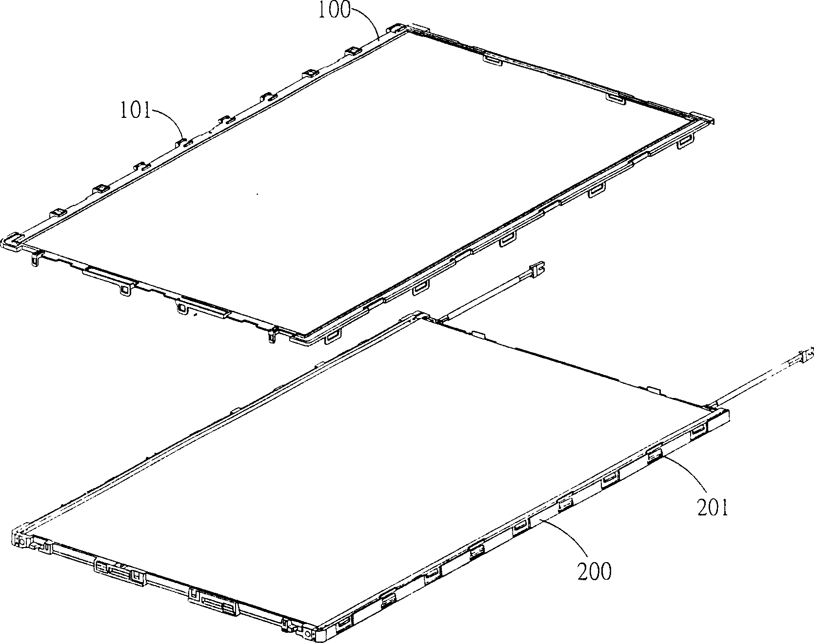
Although this "one"-shaped upper frame can achieve the purpose of saving more raw materials compared with the existing mouth-shaped upper frame, in order to achieve good fixation, the side width of the frame itself cannot be made too small, otherwise it will not be able to play its role in fixing. effect
Especially when the size of the panel is required to be larger and larger, the fixing effect of these "one"-shaped upper frames through the groove fitting force is poor, and the resistance exerted by the tolerable external torque becomes smaller, and it is easy to cause frame itself out of
Accordingly, the holding force of the "one"-shaped upper frame is still insufficient and the visible area of ​​the liquid crystal display device cannot be maintained at the same size as the traditional "mouth-shaped" upper frame.

Method used


Image

  • Side frame depression bar for liquid crystal display
  • Side frame depression bar for liquid crystal display
  • Side frame depression bar for liquid crystal display

Examples


Embodiment Construction

[0018] The above and other purposes of the present invention will become more apparent through the following detailed description of preferred embodiments in conjunction with the accompanying drawings.

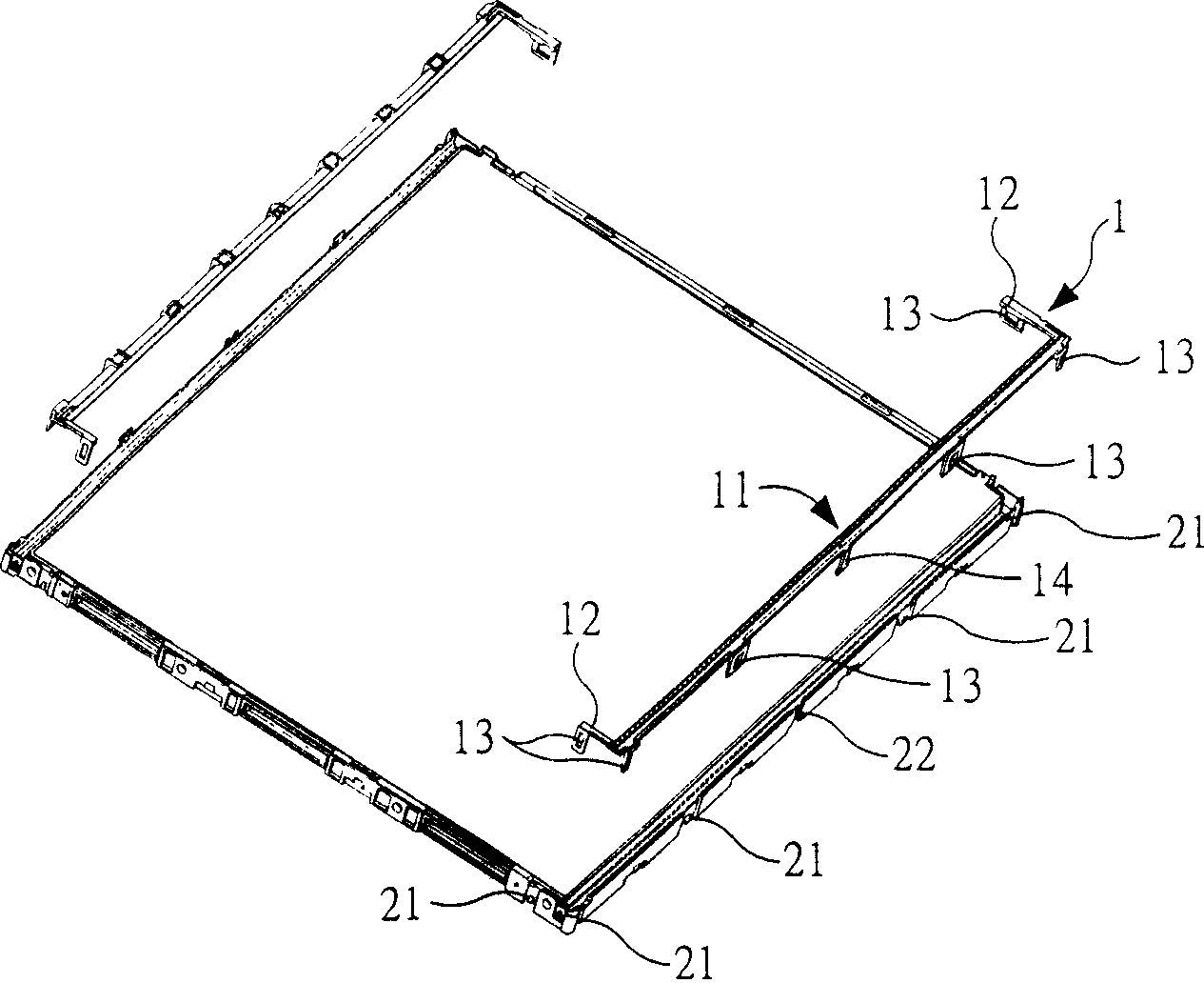
[0019] figure 2 It is a schematic diagram of the side frame bead 1 for the liquid crystal display device of the present invention and the supporting frame of the liquid crystal display device when they are not combined. image 3 The schematic view of the side frame bead 1 for liquid crystal display devices of this invention is shown. Depend on image 3 It can be seen that the side frame bead 1 for the liquid crystal display device of the present invention is mainly composed of a bead body 11 and a pair of extension parts 12 . The bead body 11 and the pair of extensions 12 form a "ㄇ" shape, and a plurality of fitting elements 13, 14 are provided on the bead body 11, and at the ends of the pair of extensions 12 are also provided with At least one fitting element 13 . The nu...


PUM


Abstract

The invention provides a side frame patand for liquid crystal display, and its characteristic: it is of a '*'-shaped structure and arranged with many inosculation components to be inosculated and fixed with a support frame of the liquid crystal display. Because of the '*'-shaped structure, it can achieve the needed fixing strength and simultaneously reduce the needed making materials, further lowering the cost.

Description

technical field [0001] The invention relates to a side frame bead for a liquid crystal display device, in particular to a side frame bead with a ㄇ-shaped structure, which is provided with a plurality of fitting elements to be embedded and fixed with a support frame used for a liquid crystal display device . Background technique [0002] With the rapid development of semiconductor technology, various electronic display devices are required to meet the requirements of lightness, thinness, shortness, and smallness as much as possible. In particular, planar display devices such as liquid crystal displays and plasma displays require high resolution, light weight, and thinness. Accordingly, the industry is committed to minimizing unnecessary assembly components. [0003] Currently, liquid crystal display devices have been widely used in desktop computers and notebook computers. The liquid crystal display panel module and the backlight module constituting the liquid crystal disp...

Claims


Application Information

Patent Timeline
Patent Type & Authority Applications(China)
IPC IPC(8): G02F1/1333
Inventor 李思汉庄永彬吕理煌萧登昆
Owner AU OPTRONICS CORP
Learn More