High-speed pressurized generator for marsh gas

A biogas generation and generator technology, applied in the direction of gas production bioreactors, waste fuels, etc., can solve the problems of small gas production, slow gas production speed, biogas generators cannot be mass-produced and promoted, and achieve stable gas source pressure , The effect of convenient refueling

Inactive Publication Date: 2005-10-26
王海金
View PDF0 Cites 2 Cited by
  • Summary
  • Abstract
  • Description
  • Claims
  • Application Information

AI Technical Summary

Problems solved by technology

[0002] Biogas is widely used in remote mountainous areas and rural areas, but currently known biogas generators have slow gas production speed and low pressure, and it is difficult to pressurize the produced gas. Most of them are used according to the pressure of biogas output, so the pressure Poor stability, small gas production per unit time, affecting the normal use of biogas appliances
In addition, general biogas generators are built underground, occupying a small area and low cost. Although it is convenient to feed materials, it is very troublesome to discharge materials. Biogas generators cannot be mass-produced and popularized, which also affects the stability of manufacturing quality. sex

Method used


Image

  • High-speed pressurized generator for marsh gas
  • High-speed pressurized generator for marsh gas

Examples


Embodiment 1

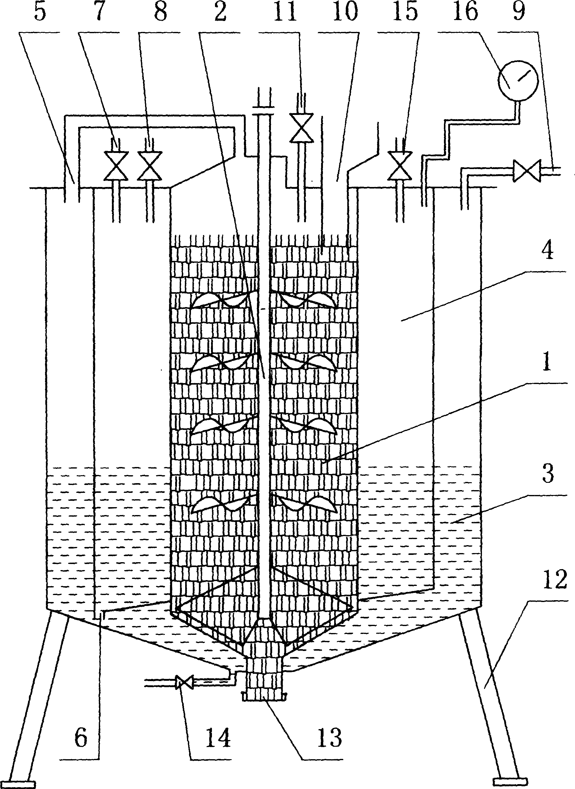
[0015] Such as figure 1 The center is a biogas generating chamber 1, in which a stirrer 2 is installed, an air storage chamber 3 is formed on the periphery of the generating chamber 1, and a pressurization chamber 4 is formed between the gas storage chamber 3 and the generating chamber 1 to generate The upper end of the chamber 1 and the air storage chamber 3 is connected through the air guide tube 5; the lower end of the air storage chamber 3 and the booster chamber 4 is connected through the downcomer 6; An air outlet pipe 9 is connected to the upper end of the gas storage chamber 3 and can be connected with a biogas appliance, and a feed inlet 10 and a water feeding pipe 11 are formed on the upper end of the generation chamber 1 . The bottom of the whole biogas high-speed pressurizable generator is shaped on a support foot 12, which is movable as a whole. An openable discharge port 13 is formed at the bottom of the generating chamber 1 . A drain valve 14 is installed at t...

Embodiment 2

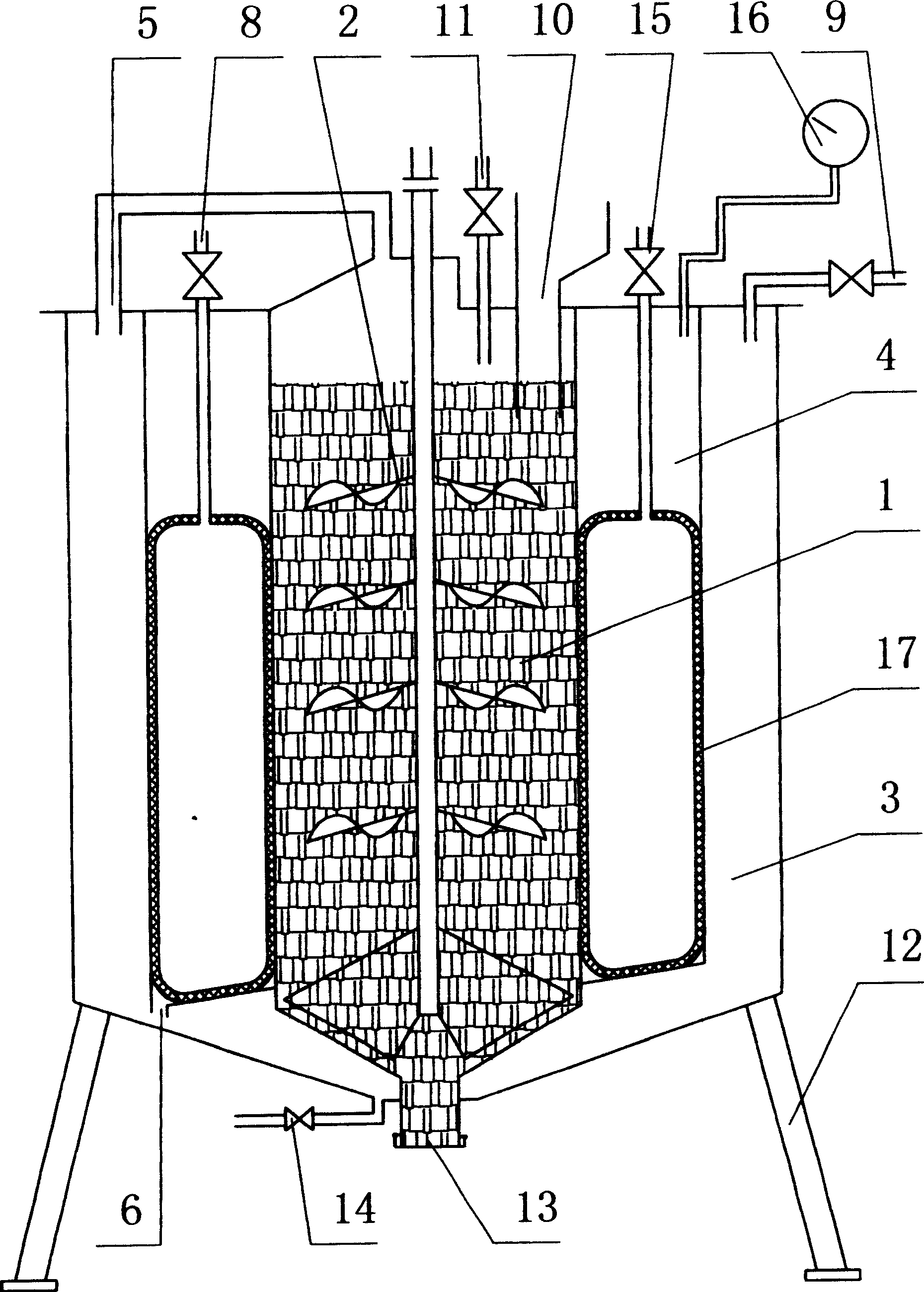
[0018] figure 2 It is a structural principle diagram of a biogas high-speed pressurizable generator equipped with a pressurized air bag in the pressurized chamber. Compared with embodiment 1, its pressurization mode is that a pressurized air bag 17 is provided in the pressurized chamber 4, and the intake pipe 8 and the deflation valve 15 communicate with the pressurized air bag 17. When the air pressure in the air storage chamber 3 was too low, the air release valve 15 was closed, and the pressurized air bag 17 in the pressurized chamber 4 was inflated by the intake pipe 8, so that the volume of the pressurized air bag 17 was increased, and the air in the pressurized chamber 4 was inflated. The biogas then enters the gas storage cavity 3 through the downcomer 6 so that the biogas pressure in the gas storage cavity 3 increases rapidly. When the biogas is not in use, the air release valve 15 can be opened to remove the air in the pressurized air bag 17, so that the space of th...


PUM


Abstract

The present invention discloses a methane generator with high speed and the pressurizing characters. Including the methane occur cavity, air storing cavity, the pressurizing cavity, the upper of the cavity and air storing cavity with the airway connected; the lower of the air store cavity and downspout with the pressurizing cavity connected; outside meeting in the pressurizing cavity has induction pipe or / and the air feeder, above termination of stores air feeder has the trachea with the methane apparatus connected, which has the cavity in upper extreme system which has aperture. Moreover, the entire methane with high speed and pressurizing generator and the base armbrace is transportable. When the inside barometric pressure of stores air cavity is excessively low, by inductionpipe either / and air feeder with turbo-charged cavity pouring water or / air, water in the pressurizing cavity passes through aqueduct again and enters stores air cavity when the space store air cavity changes small, then the methane pressure rise.

Description

technical field [0001] The invention relates to a biogas generator, in particular to a high-speed pressurized biogas generator. Background technique [0002] Biogas is widely used in remote mountainous areas and rural areas, but currently known biogas generators have slow gas production speed and low pressure, and it is difficult to pressurize the produced gas. Most of them are used according to the pressure of biogas output, so the pressure The stability is poor, and the gas production per unit time is small, which affects the normal use of biogas appliances. In addition, general biogas generators are built underground, occupying a small area and low cost. Although it is convenient to feed materials, it is very troublesome to discharge materials. Biogas generators cannot be mass-produced and popularized, which also affects the stability of manufacturing quality. sex. Contents of the invention [0003] The purpose of the present invention is to provide a generator that p...

Claims


Application Information

Patent Timeline
Patent Type & Authority Applications(China)
IPC IPC(8): C12M1/107
CPCY02E50/343Y02E50/30
Inventor 王海金
Owner 王海金
Why Eureka
Try Eureka