
Mobile communication substation based on beam switching type intelligent antenna and beam switching method

A mobile communication base station and beam switching technology, applied in the field of communication, can solve the problems of difficult beam switching control, complex mobile communication base station equipment, and inability to apply smart antennas, etc., to increase wireless communication distance, increase coverage distance, and be easy to implement Effect

Inactive Publication Date: 2005-10-26
XIAN HAITIAN ANTENNA TECH CO LTD
View PDF3 Cites 40 Cited by
  • Summary
  • Abstract
  • Description
  • Claims
  • Application Information

AI Technical Summary

Problems solved by technology

[0007] The purpose of the present invention is to provide a mobile communication base station system and a beam switching method based on a beam-switching smart antenna in order to meet the higher requirements of the PHS mobile communication system for wireless signal transmission and reception, so as to overcome the fact that the existing smart antenna cannot be moved in the PHS. The application in communication, and the existing mobile communication base station equipment are complicated, and it is not easy to realize the deficiency of beam switching control

Method used


Image

  • Mobile communication substation based on beam switching type intelligent antenna and beam switching method
  • Mobile communication substation based on beam switching type intelligent antenna and beam switching method
  • Mobile communication substation based on beam switching type intelligent antenna and beam switching method

Examples


Embodiment Construction

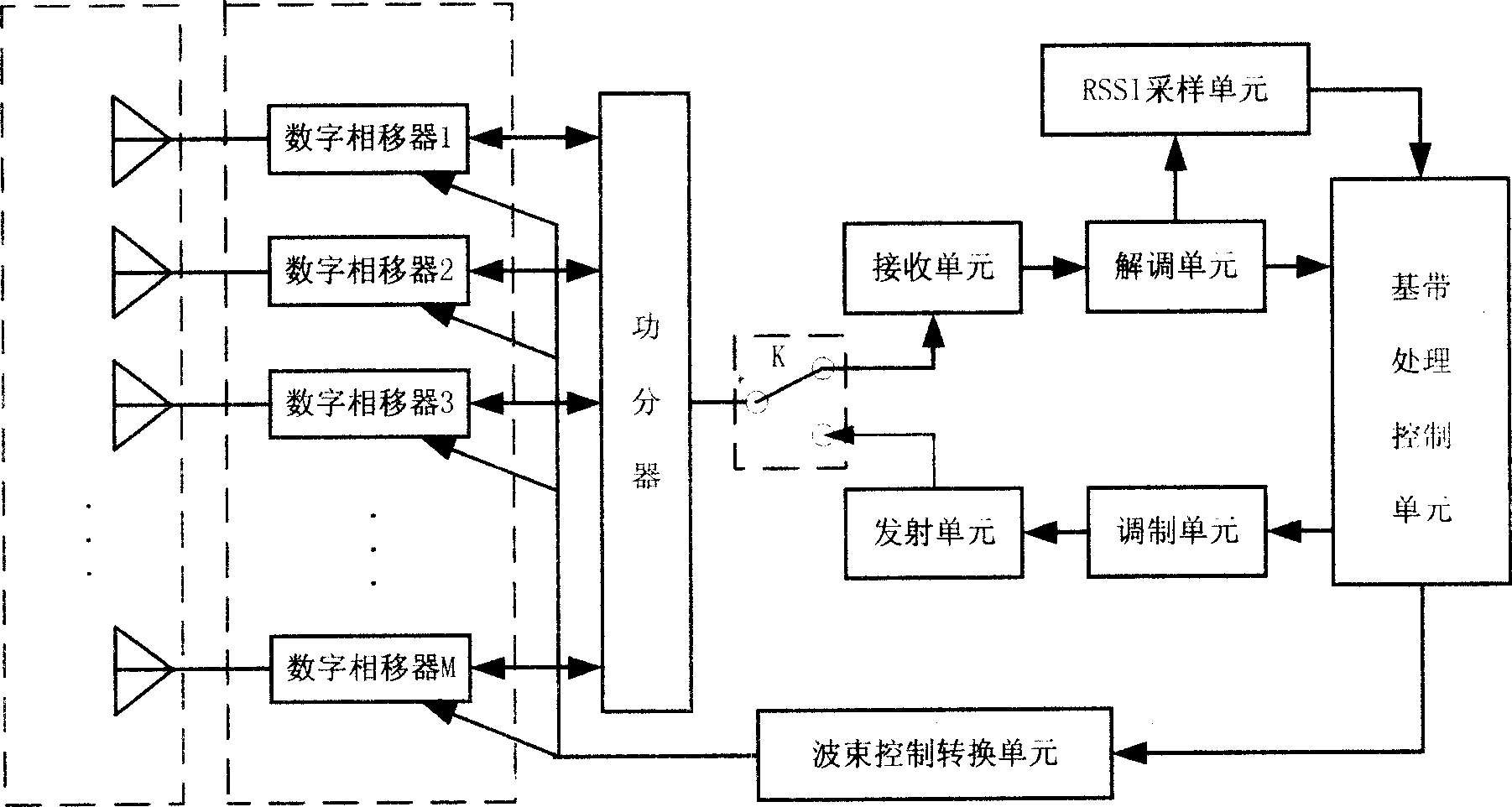
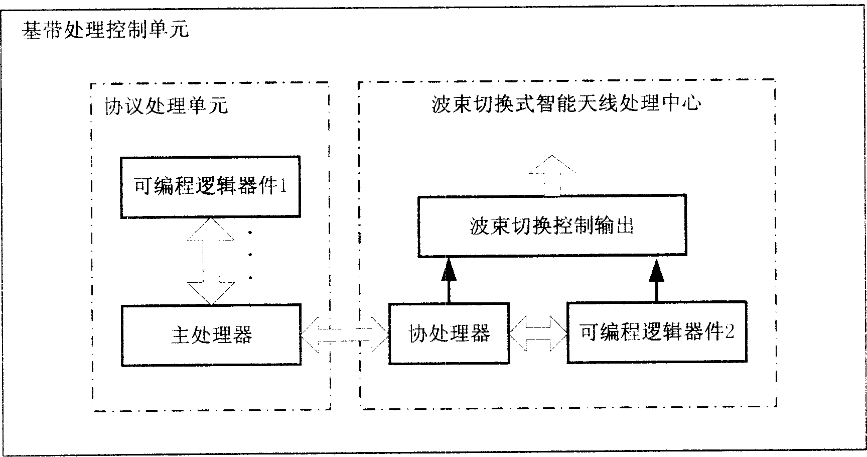
[0053] refer to figure 1 , the system of the present invention is mainly composed of a multi-unit antenna, a digital phase shifter array, a power divider beam switching antenna array, a receiving unit, a beam control conversion unit, a demodulation unit, a received signal field strength indication RSSI sampling unit, a transmitting unit, a modulation Unit, baseband processing control unit, receiving and transmitting switch K and other components. Among them: multi-element antenna, digital phase shifter array, power divider, and beam wave control conversion unit constitute four parts of the beam switching antenna array.

[0054] In the uplink stage, the power divider synthesizes multiple received signals into one signal, and in the downlink stage, distributes the transmitted signals passing through the transmitting unit to multiple antennas;

[0055] The receiving unit processes the radio frequency signal received by the antenna array, mainly including low noise amplification...


PUM


Abstract

This invention discloses a mobile communication base station and a beam switch method based on a beam switch intelligent antenna. In the up link time step, a base band control unit controls a send / receive switch at the receiving position, the received data on an antenna array enters into the receiving unit to be amplified and filtered via a digital phase shifter array and a power divider / synthesizer and demodulated and sent to the base band control unit. At the down link time step, the base band control unit controls the send / receive switch at the emit position, and sends the signal frame to be emitted to the modulation unit for modulation to be amplified by the emit unit then to be sent to the antenna array via the power divider / synthesizer, the digital phase shifter array, at the up and down link time step, the base band control unit should send the beam number to a conversion unit for timely decoding to generate a true control position then to be sent to the phase shift array to realize beam switch.

Description

technical field [0001] The invention belongs to the technical field of communication, and relates to a PHS mobile communication system of time division multiplexing (TDMA) and time division duplexing (TDD), specifically, a mobile communication base station and a beam switching method based on a beam switching smart antenna. Background technique [0002] In a wireless communication system, base stations and terminals move and propagate signals through wireless channels. Due to the influence of fading, multipath effect and other interferences in the wireless channel, the sending, receiving and processing methods of the wireless signal directly affect the performance of the communication system. [0003] Figure 13 It is a simple schematic diagram of a traditional omnidirectional antenna base station. Because this kind of base station adopts omnidirectional reception and omnidirectional transmission within the coverage area, it does not have the ability to identify the user's p...

Claims


Application Information

Patent Timeline
Patent Type & Authority Applications(China)
IPC IPC(8): H04B7/06H01Q3/26
Inventor 陈华强宗瑞良任卫军王博明李淑娟
Owner XIAN HAITIAN ANTENNA TECH CO LTD
Learn More