Vacuum coating device

A technology of vacuum coating and vacuum chamber, which is applied in the directions of vacuum evaporation coating, sputtering coating, ion implantation coating, etc., and can solve the problem of increasing the coating cycle, inconsistent characteristics of double-sided coating layers, and increasing the number of times of vacuuming, etc. problem, achieve the effect of reducing time cost, reducing the number of heating and vacuuming

Inactive Publication Date: 2005-11-02
HONG FU JIN PRECISION IND (SHENZHEN) CO LTD +1
View PDF1 Cites 12 Cited by
  • Summary
  • Abstract
  • Description
  • Claims
  • Application Information

AI Technical Summary

Problems solved by technology

[0004] However, in the existing vacuum coating equipment, only one side of the substrate can be coated at a time. If you want to coat it on both sides, you need to break the vacuum. When it needs to be cooled and taken out, turned over and then put back into the vacuum chamber, it needs to be reheated and evacuated at this time, as announced in Chinese Utility Model Patent No. 00212144.1 on March 7, 2001, which discloses a vacuum coating device, It consists of a sample holder driven by a stepping motor installed in the vacuum chamber, a target, an ion source, a heating source, a substrate holder driven by an AC speed regulating motor, and a mechanical pump and a molecular pump installed outside the vacuum chamber
Although this vacuum coating device can perform double-sided coating on the substrate by breaking the vacuum, it needs to break the vacuum, which will increase the coating cycle and the number of times of vacuuming, and cannot maintain the consistency of the parameters of the vacuum degree of the vacuum chamber. , which will make the film characteristics of the double-sided coating layer of the substrate inconsistent

Method used


Image

  • Vacuum coating device
  • Vacuum coating device
  • Vacuum coating device

Examples


Embodiment Construction

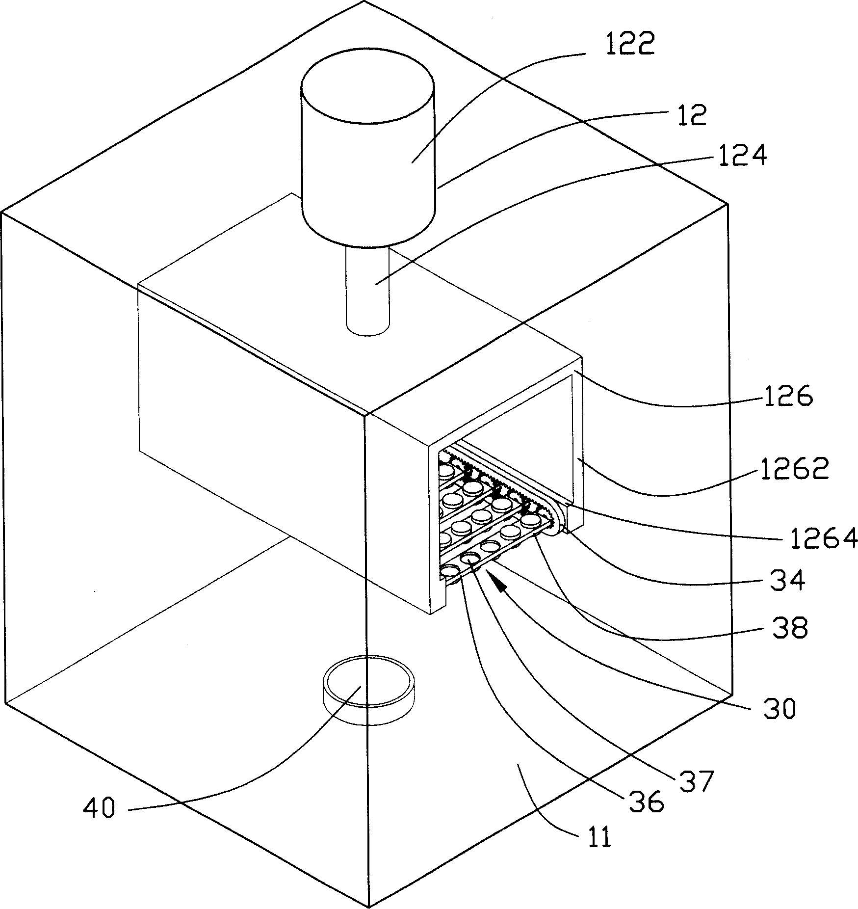
[0013] see figure 1 , The vacuum coating device 10 of the present invention comprises a vacuum chamber 11 , a rotating support assembly 12 , a substrate support frame 30 , a turning device 31 and at least one evaporation source 40 .

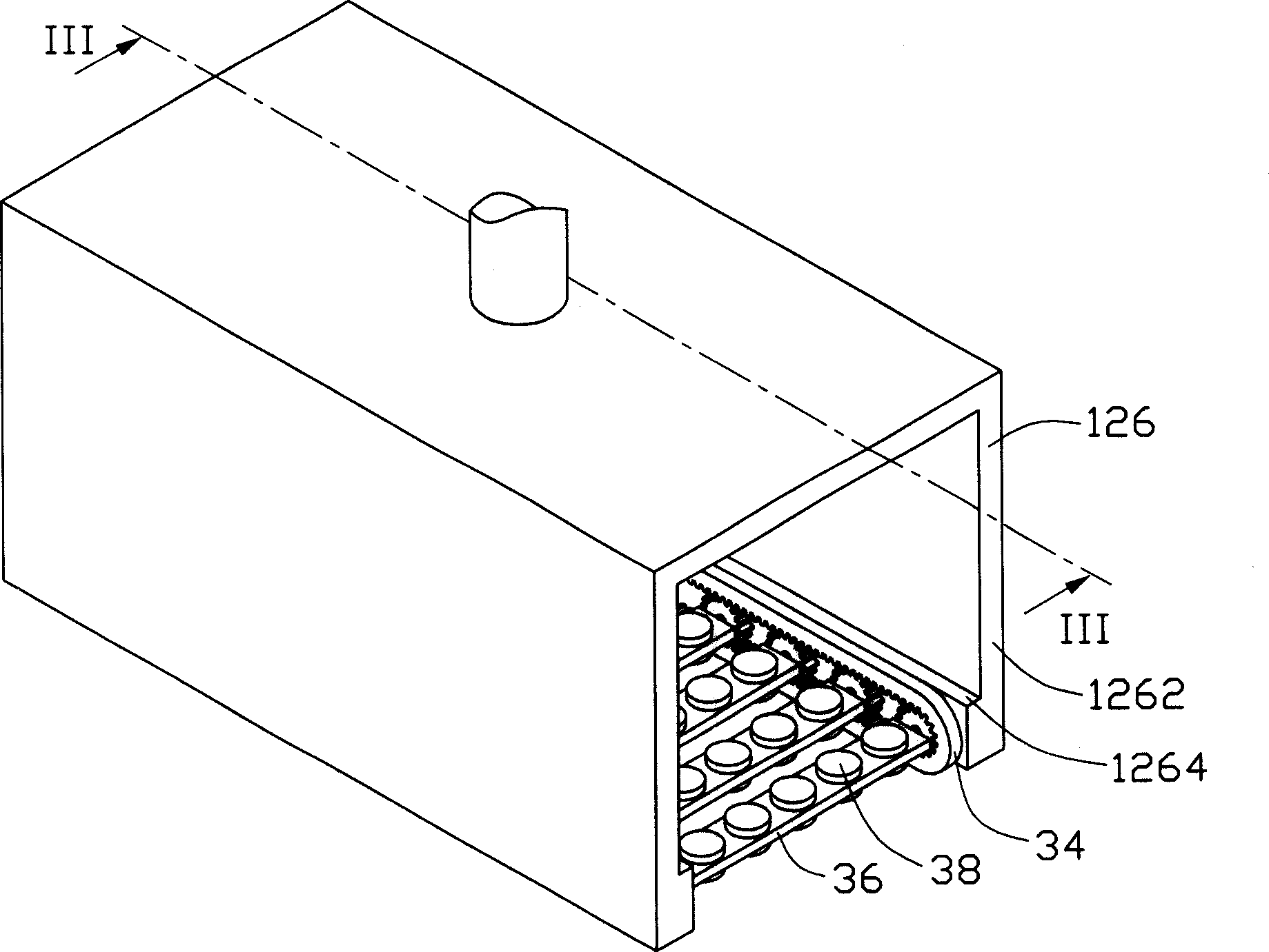
[0014] The rotating support assembly 12 includes a main motor 122, a central rotating shaft 124 and a main supporting frame 126, the main motor 122 is connected with the main supporting frame 126 through the central rotating shaft 124, and is used to drive the entire main supporting frame 126 to rotate, so that each base The film layer is uniform. In this embodiment, the main support frame 126 is square, and it includes two side walls 1262. The bottoms of the inner walls of the side walls 1262 respectively extend a longitudinal boss 1264, and a plurality of through holes ( not shown). In addition, a main motor control device is provided outside the vacuum chamber to control the rotation of the main support frame 126 .

[0015] Please also see ...


PUM


Abstract

The invention relating to a vacuum plating device, which contains a vacuum chamber, a rotation supporting assembly, a substrate support lying in vacuum chamber and containing a few substrates and also connected to rotation supporting assembly, and a deposition source lying in the vacuum chamber and opposite the substrate support, further contains a turning device lying in the vacuum chamber and connected to substrate support, and a turning control device out of the vacuum chamber, with the turning device and turning control device, several substrates rotating horizontally in the vacuum chamber. With the invented plating device, no need of cooling and breaking vacuum after one surface of the substrate is coated, the heat-up and pump-down times decrease.

Description

【Technical field】 [0001] The invention relates to a coating device, in particular to a vacuum coating device with a workpiece supporting frame which can be directly turned over in a vacuum cavity. 【Background technique】 [0002] Optical thin films basically achieve their effects through interference, which means that one or more layers of dielectric films or metal films or dielectric film stacks or metal film stacks are coated on optical components or independent substrates. Change the transmission characteristics of light waves. At present, many optical instruments, such as sensors, semiconductor lasers, interferometers, myopia glasses, sunglasses, and optical fiber communications, all require optical films. [0003] At present, the physical vapor deposition method (Physics Vapor Deposition, referred to as PVD) is the main method for optical film production. This method is to convert the film material from solid state to gaseous or ionic state. The gaseous or ionic state m...

Claims


Application Information

Patent Timeline
Patent Type & Authority Applications(China)
IPC IPC(8): C23C14/22
Inventor 黄全德黄文正
Owner HONG FU JIN PRECISION IND (SHENZHEN) CO LTD
Why Eureka
Try Eureka