Multiple choke coil and electronic equipment using the same

A technology of choke coils and coils, applied in circuits, inductors, electrical components, etc., can solve problems such as uneven inductance values, small DC resistance values, and increased heights

Inactive Publication Date: 2005-11-02
PANASONIC CORP
View PDF1 Cites 14 Cited by
  • Summary
  • Abstract
  • Description
  • Claims
  • Application Information

AI Technical Summary

Problems solved by technology

[0007] However, in the structure of the choke coil of the above-mentioned prior art, it is difficult to make the DC resistance value very small because the subsequent connection processing must be carried out on the metal terminals; Difficult to miniaturize
Furthermore, in the case of multi-phase use, there is also the problem that its characteristics cannot be fully exerted due to the uneven inductance value among multiple coils.
[0008] In addition, when an air-core coil formed

Method used


Image

  • Multiple choke coil and electronic equipment using the same
  • Multiple choke coil and electronic equipment using the same
  • Multiple choke coil and electronic equipment using the same

Examples


Embodiment 1

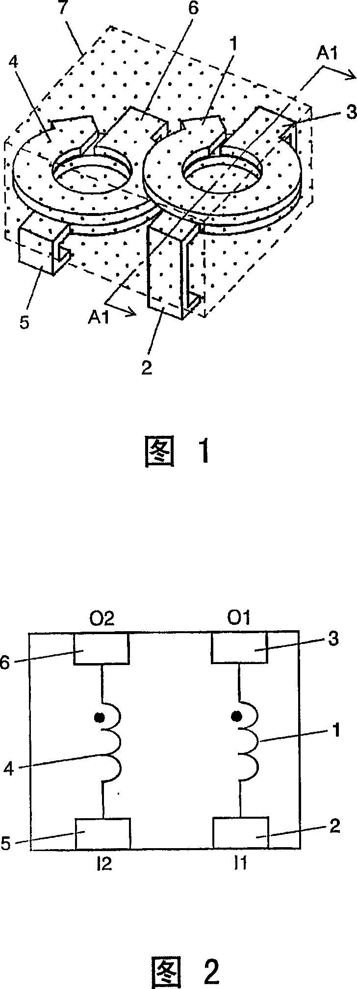
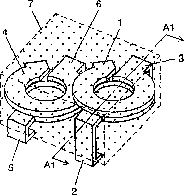
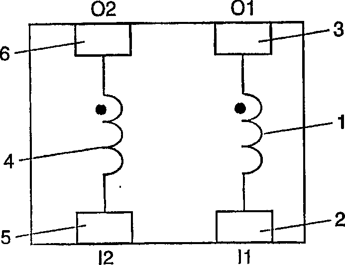
[0146] Fig. 1 is a perspective perspective view of a multiple choke coil according to Embodiment 1 of the present invention. And Figure 2 is the wiring diagram of the multiple choke coil. The first coil 1 is composed of a first input terminal 2 and a first output terminal 3 which are integrally formed. The second coil 4 is likewise composed of a second input terminal 5 and a second output terminal 6 formed integrally. The first coil 1 and the second coil 4 are wound in the same direction, and their number of turns is 1.5 turns. In this way, when current flows from the first input terminal 2 of the first coil 1 and the second input terminal 5 of the second coil 4, the directions of the magnetic fluxes in the coils of the first coil 1 and the second coil 4 are the same. direction.

[0147] In addition, the central axis of the first coil 1 and the central axis of the second coil 4 are parallel, and they are arranged such that the first coil 1 is located in the upper layer and ...

Embodiment 2

[0176] Next, a multiple choke coil according to Embodiment 2 of the present invention will be described with reference to FIGS. 7 to 10 . Although the basic structure of the multiple choke coil of this embodiment is the same as the multiple choke coil of Embodiment 1 of the present invention, the feature of this embodiment is that a terminal-integrated coil is added and arranged in a V shape. .

[0177] Fig. 7 is a perspective perspective view of the multiple choke coil of this embodiment. And Fig. 8 is the wiring diagram of this multiple choke coil. The first coil 71 integrates the first input terminal 72 and the first output terminal 73 . In the second coil 74, the second input terminal 75 and the second output terminal 76 are similarly integrated. In addition, the third coil 77 also integrates the third input terminal 78 and the third output terminal 79 . The winding direction of each coil is the same, and the number of turns is 1.5 turns. In this way, when a current f...

Embodiment 3

[0204] Next, a multiple choke coil according to Embodiment 3 of the present invention will be described with reference to FIGS. 15 and 16 . The basic structure of the multiple choke coil of this embodiment is the same as that of the multiple choke coil of the first embodiment.

[0205] Fig. 15 is a perspective perspective view of the multiple choke coil of this embodiment. The first coil 131 , the second coil 132 and the third coil 133 are the same as the coils used in the multiple choke coil of the first embodiment, and are composed of terminal-integrated coils formed by stamping and folding a metal plate. The number of turns of each coil is 2.5 turns.

[0206] Fig. 16 is a sectional view along line B2-B2 of the multiple choke coil shown in Fig. 15 . The central axis of the first coil 131, the central axis of the second coil 132 and the central axis of the third coil 133 are parallel to each other, and are arranged such that the first coil 131 and the third coil 133 are loc...


PUM

PropertyMeasurementUnit
The inside diameter ofaaaaaaaaaa
Outer diameteraaaaaaaaaa
Heightaaaaaaaaaa

Abstract

The invention is comprised of a coil group arranging a plurality of terminal-integrated type coils ( 1 ), ( 4 ) formed by bending a metal sheet in a preset development form and having a predetermined positional relationship, and a magnetic material ( 7 ) burying therein the coil group. For example, axes of the plurality of coils ( 1 ), ( 4 ) constituting the coil group, are arranged in parallel wherein the center point of at least one coil selected from the plurality of coils ( 1 ), ( 4 ) and the center point of a coil other than the selected coil are in an staggered arrangement. Due to this, an array type choke coil can be realized which is thin overall and operable with a large current in a high frequency band.

Description

technical field [0001] The invention relates to multiple choke coils used in various electronic equipment and electronic equipment using the multiple choke coils, especially power supply equipment. Background technique [0002] For inductors such as choke coils, miniaturization and thinning are desired in order to match the miniaturization and weight reduction of electronic equipment. In addition, in response to the increase in speed and high integration of LSIs such as CPUs, it is desired that inductors can be used with large currents of several A to tens of A in the high frequency range. [0003] Therefore, it is desired to inexpensively provide an inductor having the following characteristics: having a small size and a small resistance to suppress heat generation, a small loss in a high-frequency band, and an inductance due to DC superimposition even in the case of a large current. The decrease in value is also small. [0004] Recently, in converters such as DC / DC, a ci...

Claims


Application Information

Patent Timeline
IPC IPC(8): H01F37/00
Inventor 松谷伸哉今西恒次植松秀典
Owner PANASONIC CORP
Why Eureka
Try Eureka