Sputtering target and sputtering method using the target

A sputtering and sputtering device technology, applied to the sputtering target and the sputtering field using the target, can solve the problems of reproducibility of film formation, abnormal discharge, particle generation, etc., to prevent abnormal discharge and particles production, high target service efficiency, and high film formation reproducibility

Active Publication Date: 2014-09-17
ULVAC INC
View PDF7 Cites 0 Cited by
  • Summary
  • Abstract
  • Description
  • Claims
  • Application Information

AI Technical Summary

Problems solved by technology

[0006] In this case, if the non-corroded area remains on the outer periphery of the target, abnormal discharge will be induced due to charging, or the film redeposited on the non-etched area will generate particles on the substrate surface
This affects the reproducibility of film formation and reduces target service efficiency

Method used


Image

  • Sputtering target and sputtering method using the target
  • Sputtering target and sputtering method using the target
  • Sputtering target and sputtering method using the target

Examples


Embodiment 1

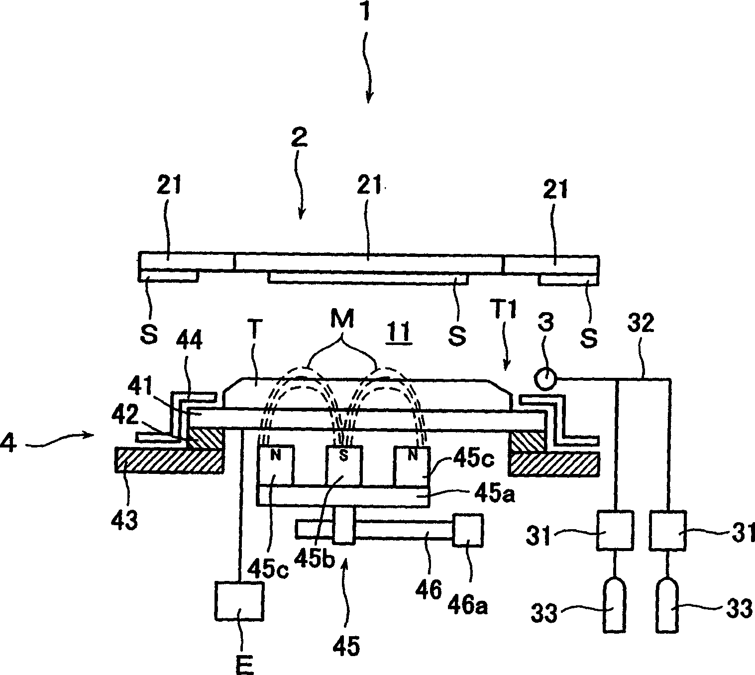
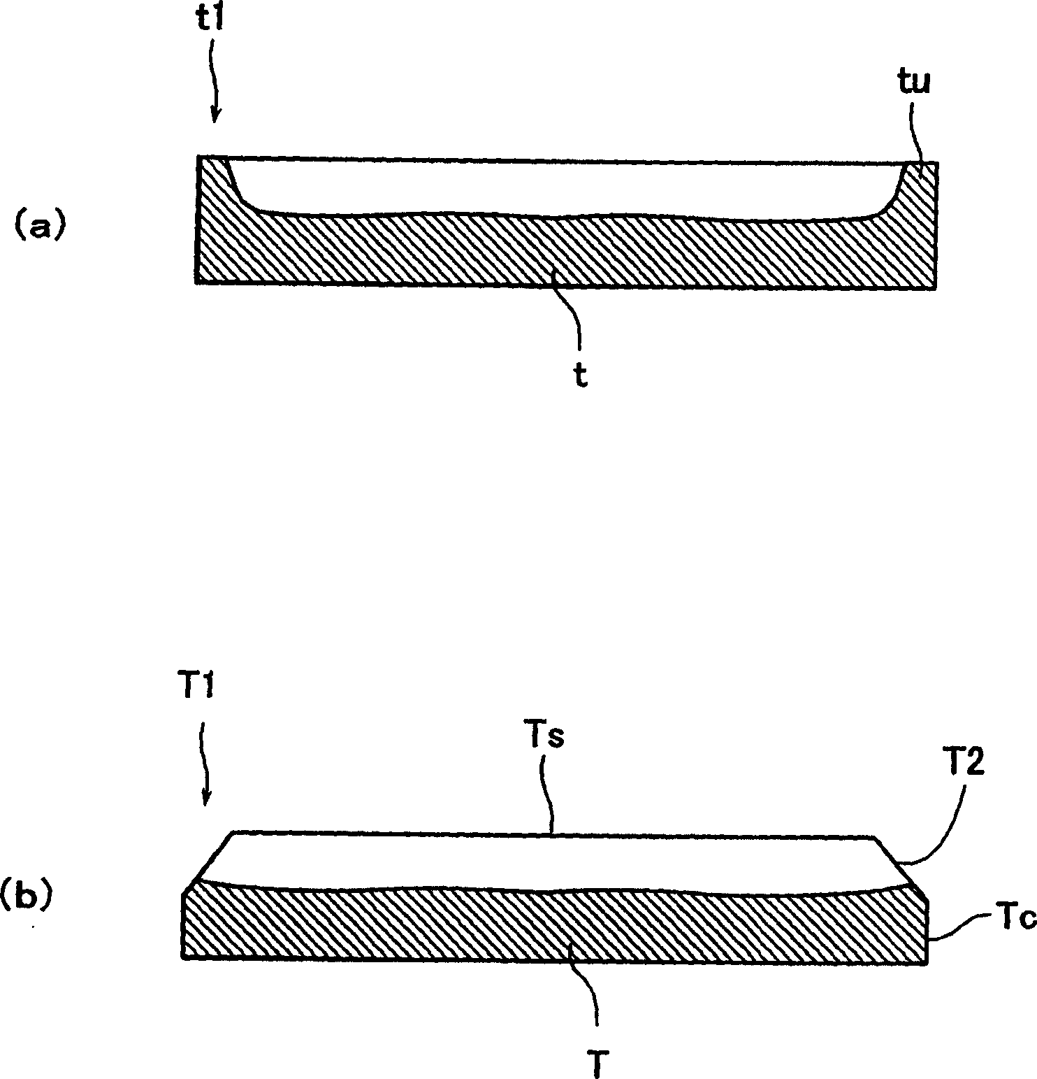
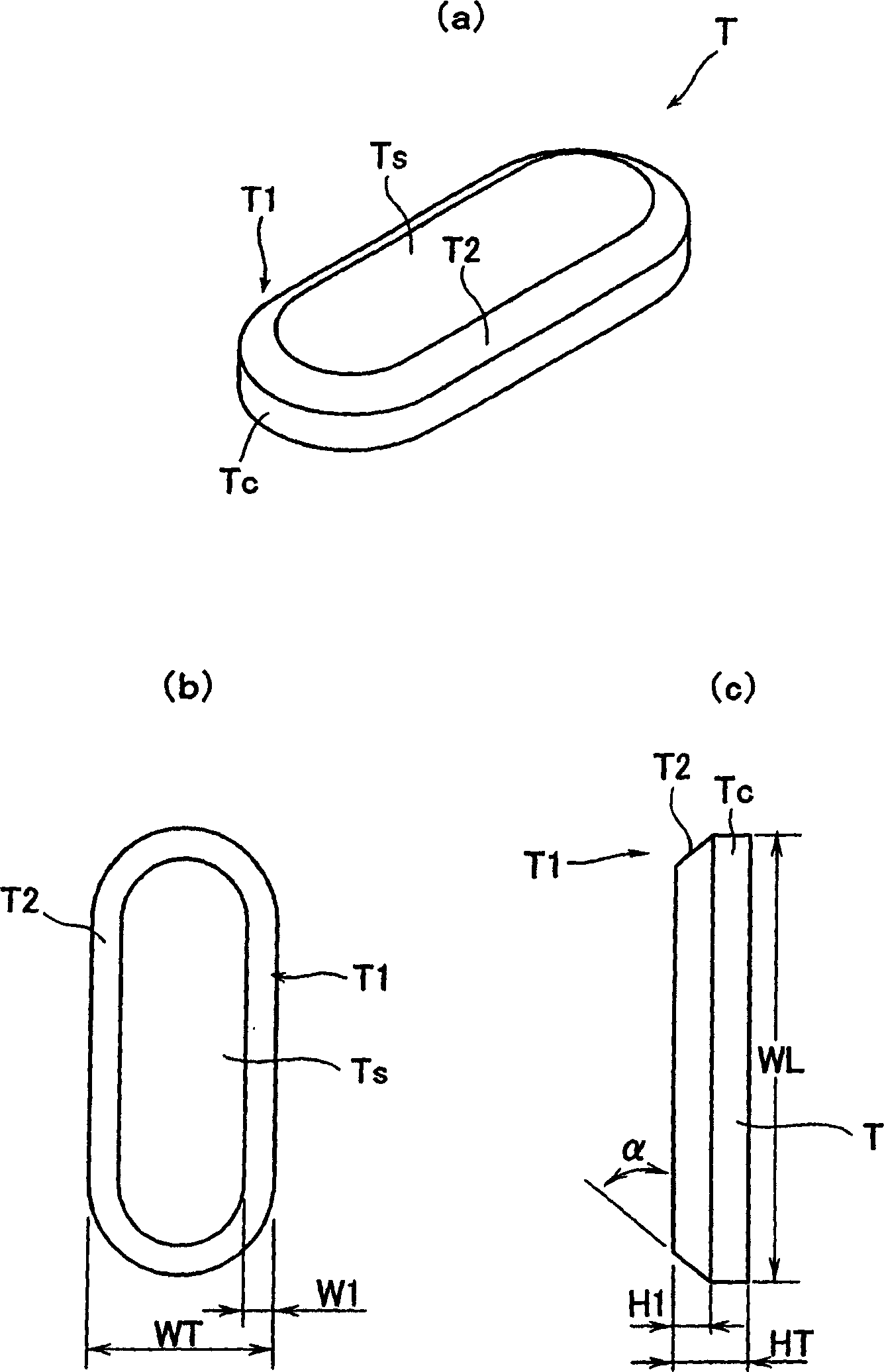
[0042] According to Example 1, the target T was formed from Si into an oblong configuration with a major axis WL (300 mm), a minor axis WT (125 mm) and a height HT (10 mm) by using a known method. Then a bevel, ie a sloped surface T2 with a side width W1 (20 mm) and a height H1 (5 mm), is formed on the target and finally attached to the back plate 41 .

[0043] The target T is mounted on the sputtering device 1 , and then the glass substrate S is transferred to a position opposite to the target T by a vacuum transfer device 21 .

[0044] Under sputtering conditions, the pressure in the sputtering chamber 11 is maintained at a vacuum of 0.4 Pa and argon as a sputtering gas and nitrogen as a reactive gas are introduced into the sputtering chamber under the control of a mass flow controller 31 In step 11, a silicon nitride film is continuously deposited on a glass substrate. In this case, the distance between the target T and the glass substrate was set to 90 mm. Figure 5 Line...


PUM


Abstract

A sputtering target and a sputtering method using the same. In prior art sputtering target configurations, during plasma generation by applying a negative DC voltage or high frequency voltage to the target, current flow from the target to the grounded shield results. Therefore, there arises a problem that a non-eroded area of ​​the target periphery remains without being sputtered because plasma is not generated on the peripheral surface of the target. This can result in the formation of particles on the substrate surface due to charge-induced abnormal discharge, or by redepositing the film on non-etched areas, which affects the reproducibility of film formation, reducing the service effectiveness of the target. Such a problem can be solved by the present invention in which the inclined surface (T2) surrounding the target (T) body is formed on the region where the sputtering surface (Ts) and the peripheral surface (Tc) of the target (T) body cross each other.

Description

technical field [0001] The present invention relates to a target for sputtering and a sputtering method using the same, and more particularly, to a target for a magnetron type sputtering apparatus and a sputtering method using the same. Background technique [0002] In magnetron-type sputtering, it is possible to increase the density of the plasma by arranging behind the target a magnet assembly with an array of magnets with alternating poles, which is used to form a tunnel-shaped sputtering surface in front of the target Magnetic flux, and capture electrons ionized in front of the sputtering surface and secondary electrons generated by sputtering to increase the density of electrons on the sputtering surface and increase the probability of these electrons colliding with noble gas molecules. Therefore, magnetron type sputtering has advantages such as an increase in the speed of forming a deposited film, and thus is used to form a predetermined thin film on a substrate to be ...

Claims


Application Information

Patent Timeline
Patent Type & Authority Patents(China)
IPC IPC(8): C23C14/34C23C14/35
CPCC23C14/3407H01J37/3405H01J37/3423H01J37/3426
Inventor 新井真石桥晓小松孝谷典明清田淳也太田淳杉浦功中村久三
Owner ULVAC INC
Why Eureka
Try Eureka