

Method for manufacturing pistons of compressor
A technology for compressors and pistons, which is applied in the field of piston processing, and can solve problems such as high requirements, increased manufacturing difficulty, and high requirements
- Summary
- Abstract
- Description
- Claims
- Application Information
AI Technical Summary
Problems solved by technology
Method used
Image

Examples
Embodiment Construction
[0015] Processing method one:
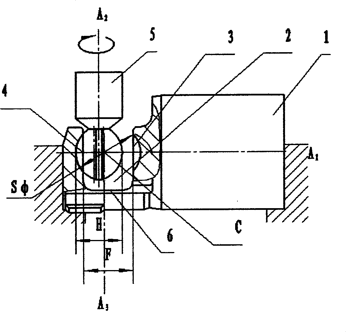
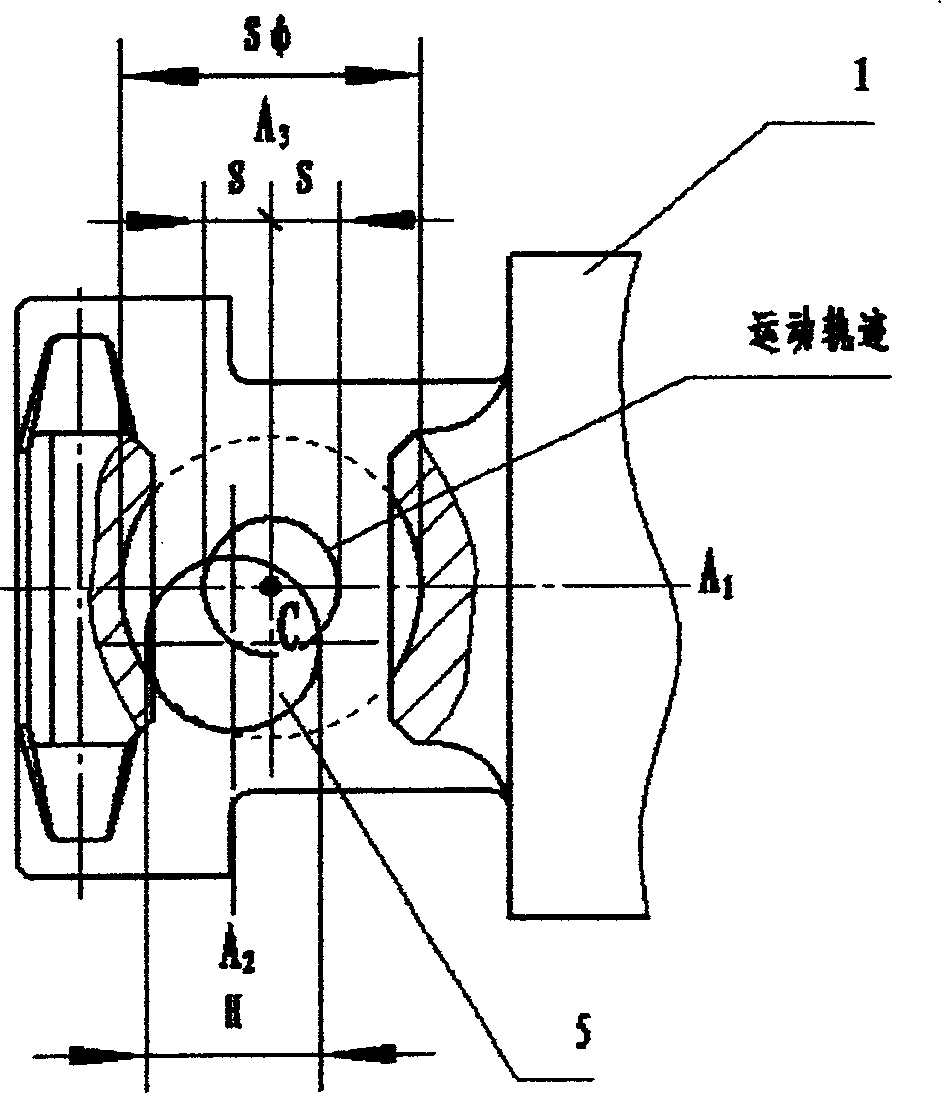
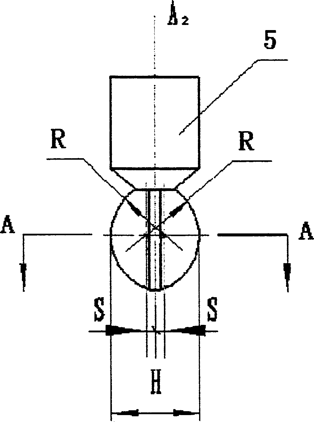
[0016] exist figure 1 , figure 2 , image 3 , Figure 4 In, a method for machining a variable displacement compressor piston, wherein the piston 1 includes a slot 2 for receiving a drive plate, the slot 2 includes a pair of opposing walls 3 and 4, and wherein each wall Having a spherical groove for slidably supporting one of the shoes, the method comprises: placing a tool with a cutter 5 between the walls of the slot 2; during machining, the piston 1 is stationary and the cutter 5 Relative to the piston 1 around the predetermined sphere positioning point as the center of circle to perform circular motion on the same plane, the circular surface formed by the circular motion is parallel to the inner wall surface 6 of the slot 2 connecting the opposite walls 3 and 4 of the slot 2, the described The spherical positioning point of the piston is located on the longitudinal axis A1 of the piston, and the cutter is rotated around its own central ax...
PUM
 Abstract
Description
Claims
Application Information