Mode for inpouring fuel into future tokamak type thermonuclear reactor power station

A fusion reactor and power station technology, applied in fusion reactors, thermonuclear fusion reactors, nuclear reactors, etc., can solve the problems of physical and chemical changes in liquid fuels, low efficiency, and impracticality

Inactive Publication Date: 2005-11-16
INST OF PLASMA PHYSICS CHINESE ACAD OF SCI
View PDF0 Cites 10 Cited by
  • Summary
  • Abstract
  • Description
  • Claims
  • Application Information

AI Technical Summary

Problems solved by technology

If liquid fuel injection is used, the liquid fuel will inevitably pass through the high-temperature cladding area, the heat transfer of the pipeline is very serious, and the liquid fuel may even undergo physical and chemical changes, which is not practical
If the current most devices are used, the low-pressure inert gas flow is directly charged, because the nozzle must be designed inside the vacuum chamber of the device, and the efficiency is very low, the maximum can only reach 20%. If it is used in the future fusion reactor, once a long time The delivery pipeline is less efficient

Method used


Image

  • Mode for inpouring fuel into future tokamak type thermonuclear reactor power station
  • Mode for inpouring fuel into future tokamak type thermonuclear reactor power station
  • Mode for inpouring fuel into future tokamak type thermonuclear reactor power station

Examples


Embodiment Construction

[0016] see figure 1 ~ Figure 6.

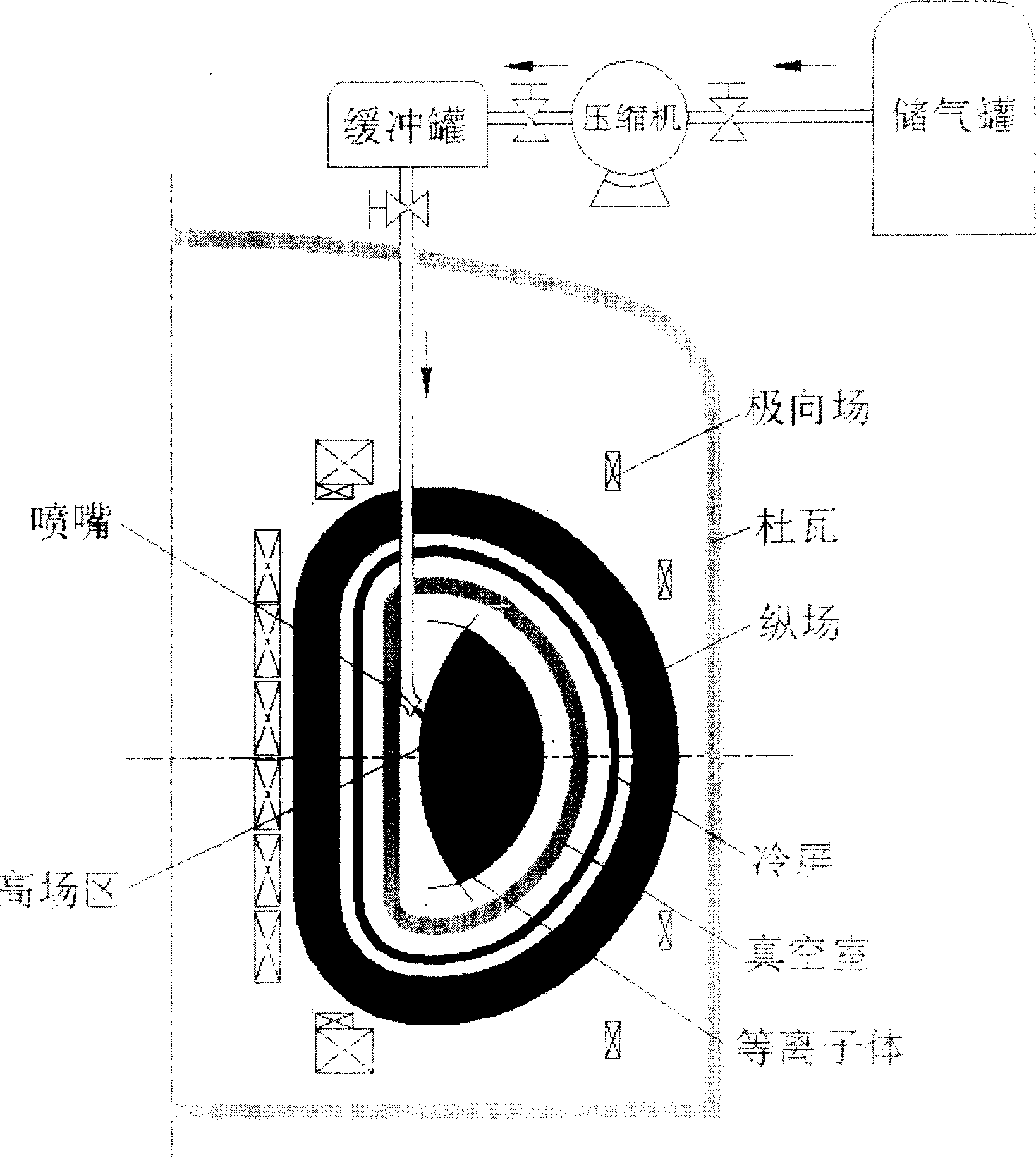
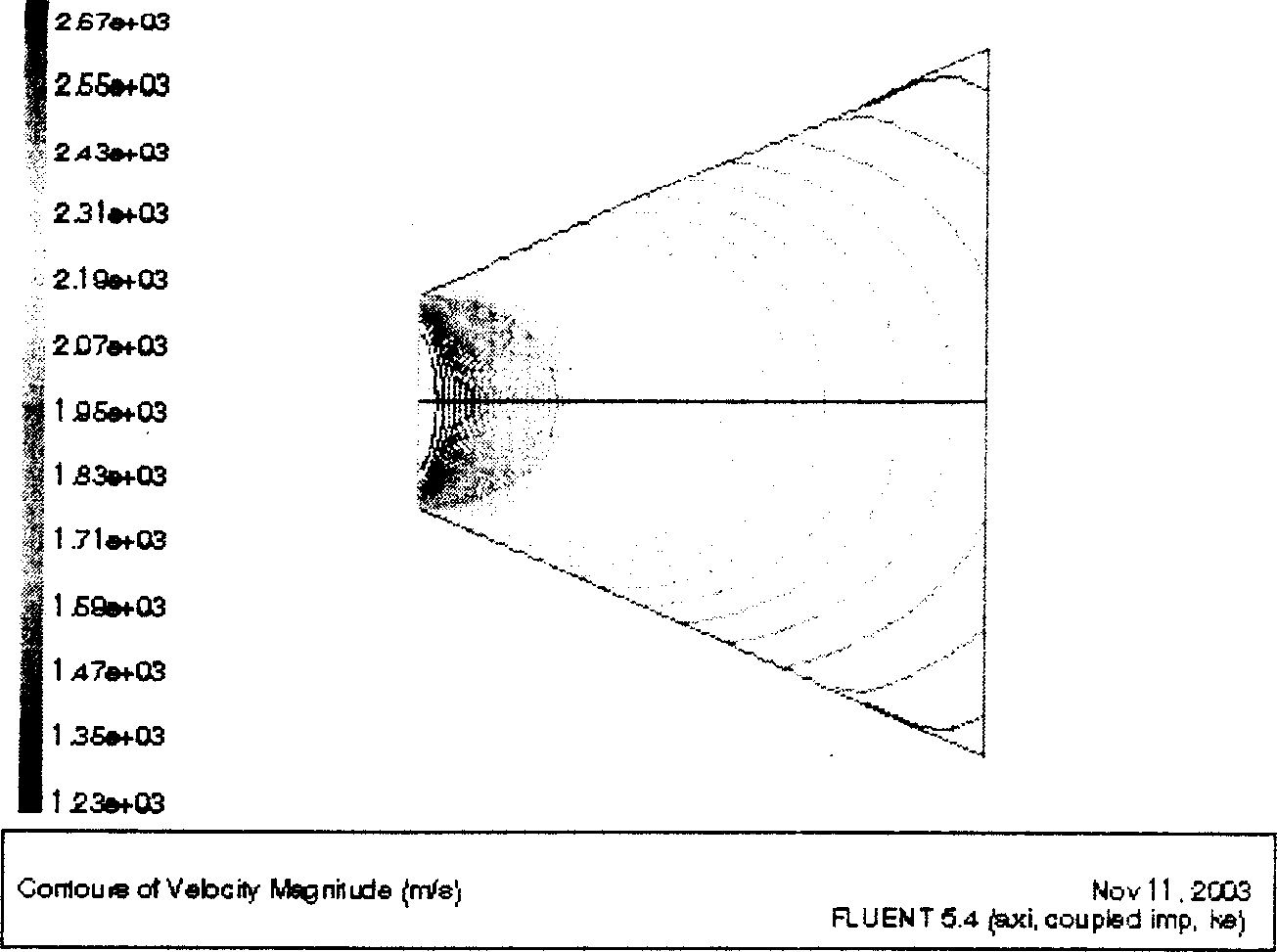
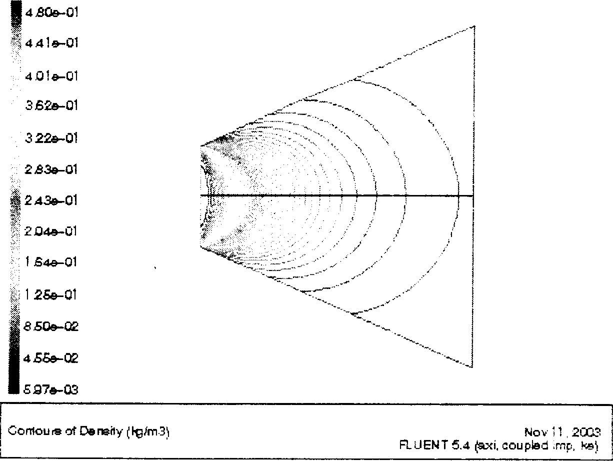
[0017] The gas path process of the fuel injection method of the Tokamak fusion reactor power station is: first, the fusion reactor fuel gas is stored in a low-pressure gas storage tank, and then passes through the compressor. The gas flow pressure is raised to 100 atmospheres, stored in the buffer tank, and finally by Valve control, through the Lava nozzle, the airflow passes through the nozzle shrinkage neck, first compressed, and then rapidly expanded, the maximum speed airflow can reach 2670m / s, the Mach number reaches 5, and enters the plasma high field area. The plasma distance from the nozzle to the edge of the plasma area is 20cm, the distance from the buffer tank to the nozzle is 5m, and the pipe diameter is 10mm.

[0018] For the plasma and its edge area, the sound velocity of particles is used. Its value is not 340m / s in the air, which changes with the temperature and vacuum of the plasma area. In the central area of ​​the plasma, t...


PUM


Abstract

A fuel injection mode of future Tokamak fusion reactor is featured as transporting high pressure fuel gas of fusion reactor to high lift region of vacuum chamber through piping, setting a Lavel nozzle at tail end of piping to let gas stream speed be supersonic speed at outlet of nozzle and then entering plasma high lift region. The high efficiency of fuel injection can be realized by the designed mode.

Description

technical field [0001] The invention belongs to a nuclear fusion reactor fuel injection technology, in particular to a fuel injection technology for a tokamak fusion reactor. Background technique [0002] In the operation of the existing large and medium-sized tokamak devices, in order to suppress and reduce the damage to the divertor and other structures of the device due to plasma rupture, or ensure the soft landing of the plasma when the device stops operating, so as not to bring extreme damage to the device Large destruction and fuel replenishment during plasma discharge are usually sprayed into the plasma region with projectiles (solid inert gas), liquid inert gas or directly filled with low-pressure inert gas flow (GAS PUFFER). However, these fuel injection methods have certain defects for future fusion reactors. The projectile injection method can only be a linear trajectory, which is impractical for future fusion reactor power plants, because the projectiles must be ...

Claims


Application Information

Patent Timeline
Patent Type & Authority Applications(China)
IPC IPC(8): G21B1/00
CPCY02E30/122Y02E30/10
Inventor 宋云涛
Owner INST OF PLASMA PHYSICS CHINESE ACAD OF SCI
Why Eureka
Try Eureka