Controllable discharge switch of high-energy impulse in three electrodes under vacuum environment

A high-energy pulse and vacuum environment technology, applied in electric switches, high-voltage/high-current switches, circuits, etc., can solve problems such as electrode ablation, difficult to meet requirements, and narrow switching range

Inactive Publication Date: 2005-11-16
XI AN JIAOTONG UNIV
View PDF0 Cites 34 Cited by
  • Summary
  • Abstract
  • Description
  • Claims
  • Application Information

AI Technical Summary

Problems solved by technology

[0003] Under the action of high-energy pulse arc, the current pulse discharge switch has narrow action range, poor stability, serious electrode ablation, and short working life. Under the condition of long life, it is difficult to meet the requirements

Method used


Image

  • Controllable discharge switch of high-energy impulse in three electrodes under vacuum environment
  • Controllable discharge switch of high-energy impulse in three electrodes under vacuum environment
  • Controllable discharge switch of high-energy impulse in three electrodes under vacuum environment

Examples


Embodiment 1

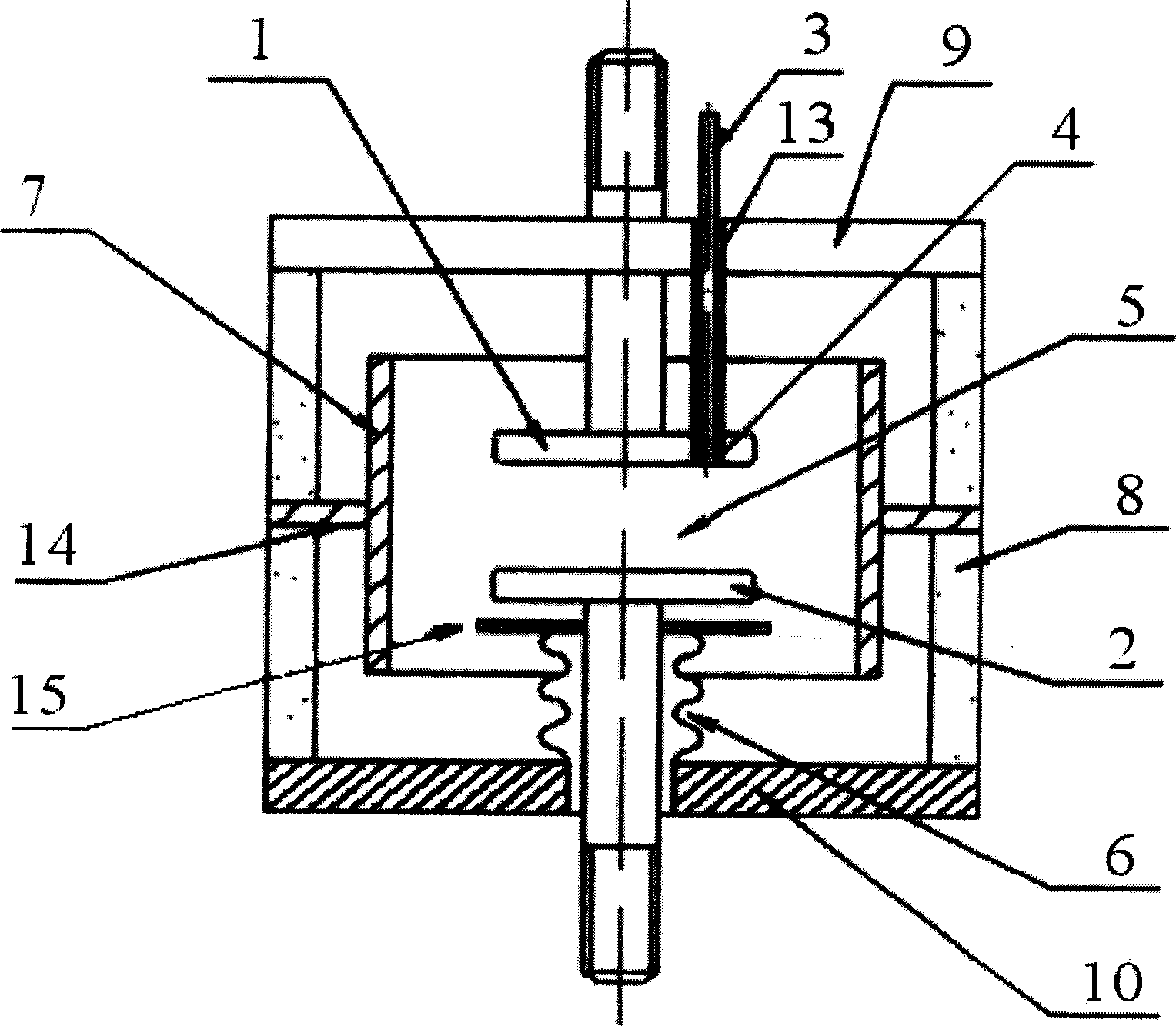
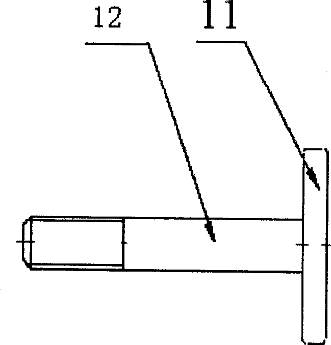
[0015] Example 1, see figure 1 , 2, this embodiment includes an insulating shell 8 and an upper electrode 1 and a lower electrode 2 composed of a contact 11 and a conduction part 12 arranged in the insulating shell 8, and the upper electrode 1 and the lower electrode 2 pass through the end flange 9 and the The end flange 10 is arranged in the insulating shell 8, and the pressure in the airtight housing formed by the insulating shell 8 and the end flanges 9 and 10 arranged at both ends of the insulating shell 8 is 10 -3 ~10 -4 Pa, the upper electrode 1 is a fixed electrode, and an insulating tube 13 inlaid with a columnar trigger electrode 3 is opened in the upper electrode 1. A discharge gap 4 is formed between the columnar trigger electrode 3 and the insulating sleeve 13, and the lower electrode 2 is a movable electrode. The lower electrode 2 is connected to the end flange 10 through the bellows 6, the upper end of the bellows 6 is also provided with a bellows shield 15, the...

Embodiment 2

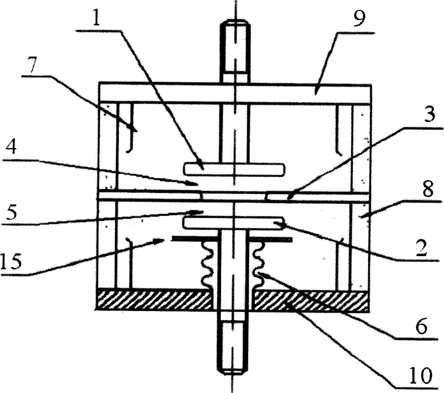
[0017] Example 2, see image 3 , this embodiment includes an insulating shell 8 and an upper electrode 1 and a lower electrode 2 composed of a contact 11 and a conduction part 12 arranged in the insulating shell 8, and the upper electrode 1 and the lower electrode 2 pass through the end flange 9 and the end method The flange 10 is arranged in the insulating shell 8, and the pressure in the airtight shell formed by the insulating shell 8 and the end flanges 9 and 10 arranged at both ends of the insulating shell 8 is 10 -3 ~10 -4 Pa, the upper electrode 1 is a fixed electrode, the lower electrode 2 is a movable electrode, the lower electrode 2 is connected to the end flange 10 through the bellows 6, the upper end of the bellows 6 is also provided with a bellows shield 15, and the bellows shield 15 It can prevent metal vapor from depositing on the bellows 6, affecting the characteristics and life of the bellows 6. An annular trigger electrode 3 is arranged between the discharge ...

Embodiment 3

[0019] Embodiment 3: see Figure 4 , this embodiment includes an insulating shell 8 and an upper electrode 1 and a lower electrode 2 composed of a contact 11 and a conduction part 12 arranged in the insulating shell 8, and the upper electrode 1 and the lower electrode 2 pass through the end flange 9 and the end method The flange 10 is arranged in the insulating shell 8, and the pressure in the airtight shell formed by the insulating shell 8 and the end flanges 9 and 10 arranged at both ends of the insulating shell 8 is 10 -3 ~10 -4 Pa, the upper electrode 1 and the lower electrode 2 are movable electrodes, which are respectively connected to the end flanges 9 and 10 through the bellows 6. The upper end of the bellows 6 is also provided with a bellows shield 15, which can prevent metal Vapor is deposited on the bellows 6, which affects the characteristics and life of the bellows 6. Around the upper electrode 1, the lower electrode 2 and the trigger electrode 3, a shielding cov...


PUM


Abstract

The disclosed discharge switch includes upper and lower electrodes setup inside insulated case. Pressure inside the air locked shell body formed by the insulated case and flanges at two ends of the case is 10 -3 - 10 -4 Pa. At least one of the upper and lower electrodes is a movable electrode. Trigger electrode is inlaid inside the fixed electrode or setup between the upper and lower electrodes. Since being air locked in vacuum environment, the upper and lower electrodes possess tremendous ability of ducting transient current in high energy. Moreover, operation reliability of pulse switch is raised because vacuum environment is not interfered from outside. Features are: raised reliability, very low ablation rate of electrode, and wide range of stable operation voltage.

Description

technical field [0001] The invention relates to a high-energy discharge switch, in particular to a controllable three-electrode high-energy pulse discharge switch in a vacuum environment for pulse power technology, nuclear fusion, high-energy laser and high-energy pulse current tests. Background technique [0002] The high-energy pulse discharge switch is one of the key devices commonly used in pulse power technology, nuclear fusion, high-energy laser and high-energy pulse technology. The domestic discharge switch used in pulse power technology generally has a charge transfer of about 0.2 coulombs. Foreign pulse power technology In the research, the single charge transfer of the discharge switch has reached 1 coulomb. With the development of strong electromagnetic pulse technology such as pulse power technology, high-energy pulse generators will play an increasingly important role, and the amount of charge transfer and pulse energy that pass through the discharge switch in a...

Claims


Application Information

Patent Timeline
Patent Type & Authority Applications(China)
IPC IPC(8): H01H33/66
CPCH01T2/02H01T4/12
Inventor 姚学玲陈景亮孙伟刘东社
Owner XI AN JIAOTONG UNIV
Why Eureka
Try Eureka