Antenna mounting printed-circuit board

A technology for printed circuit boards and antennas, which is applied to printed circuit components, including printed electrical components, antennas, etc., can solve the problems of limited freedom in printed circuit board layout design and hinder the miniaturization of devices, and achieve substantial miniaturization , Avoid bandwidth narrowing, and solve the effect of reducing impedance value

Inactive Publication Date: 2005-12-07
DEXERIALS CORP
View PDF2 Cites 0 Cited by
  • Summary
  • Abstract
  • Description
  • Claims
  • Application Information

AI Technical Summary

Problems solved by technology

It is obvious that the above-mentioned method hinders the miniaturization of the device, indicating that the freedom of layout design on the printed circuit board is greatly limited

Method used


Image

  • Antenna mounting printed-circuit board
  • Antenna mounting printed-circuit board
  • Antenna mounting printed-circuit board

Examples


Embodiment Construction

[0040] Next, specific embodiments of the present invention will be described with reference to the drawings.

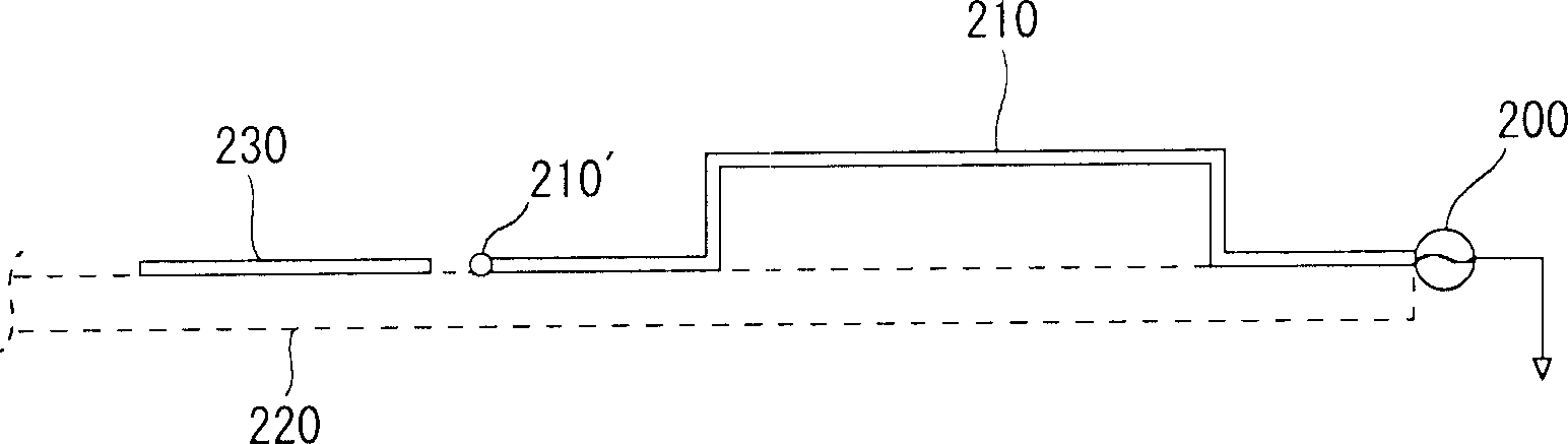
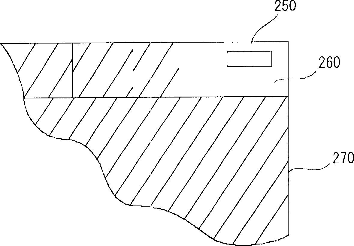
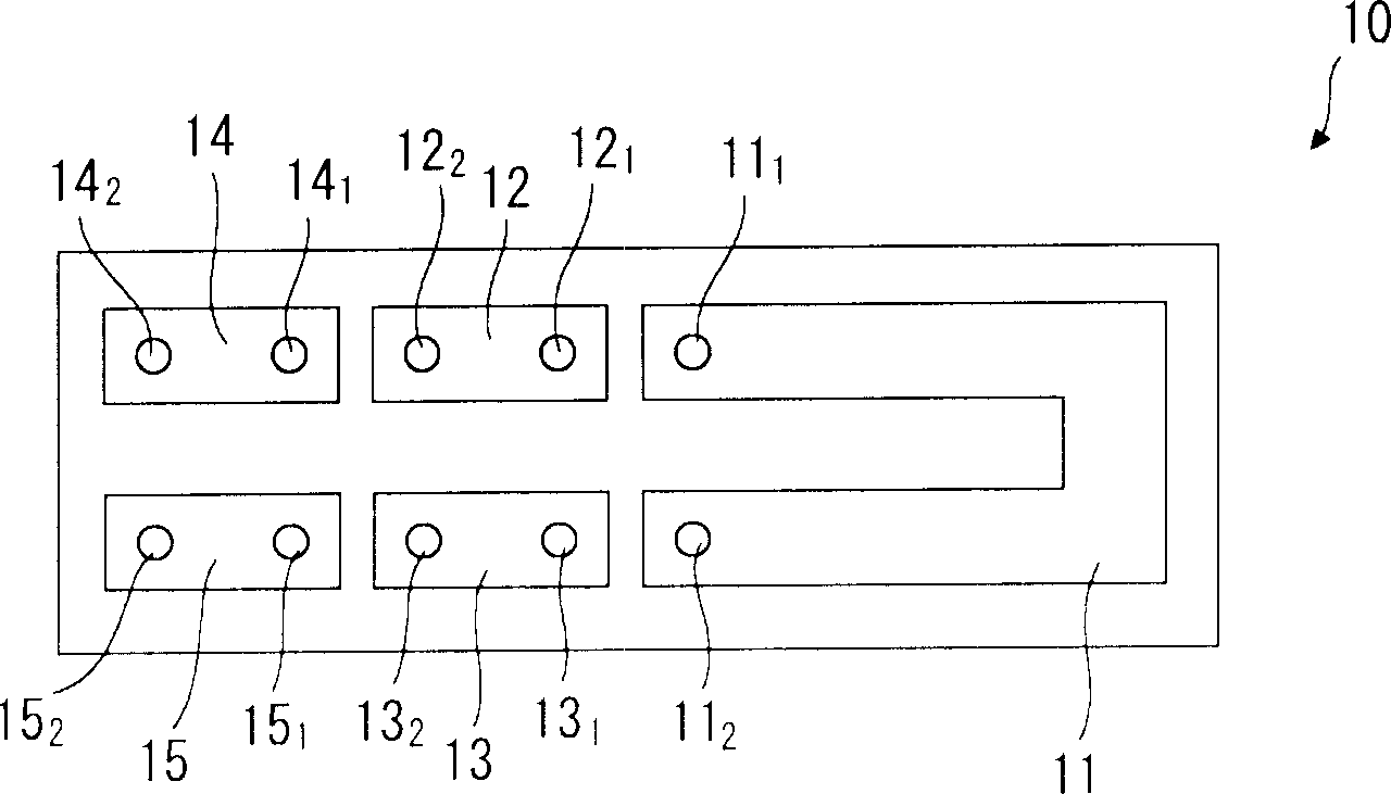
[0041] The present embodiment relates to a printed circuit board which can be loaded in a mobile communication device such as a mobile phone or a device having at least a communication function such as a wireless local area network (LAN) according to the Institute of Electrical and Electronics Engineers (IEEE) 802.11 standard, On this printed circuit board is mounted a chip antenna element, that is, a so-called printed antenna, in which an antenna conductor is patterned on a specific resin substrate as a base material. In the printed circuit, the printed antenna and one or more other modules used to realize the functions of the device body are installed, and the printed antenna is not easily disturbed by the surrounding ground plane, and even actively uses the surrounding ground plane to complete the electrical performance. match, and achieve good directionality. Thu...


PUM


Abstract

A printed circuit board (50) includes a chip-shaped printed antenna (10) having an open end formed by at least two antenna conductors arranged separately from each other. As shown by a hatched portion, on the printed circuit board (50), a ground required by one or more other modules is arranged so as to surround a region around the printed antenna (10) excluding a certain region. Thus, on the printed circuit board (50), the radiation electric field does not become a dipole mode but is formed to discharge in one direction in a balloon shape as shown by a broken line.

Description

technical field [0001] The present invention relates to an antenna-mounted printed circuit board mounted on a device having at least a communication function, on which various modules performing various functions are mounted. Background technique [0002] In recent years, various wireless communication technologies such as mobile communication devices such as mobile phones or wireless local area networks (LAN) based on the Institute of Electrical and Electronics Engineers (IEEE) 802.11 standard have been rapidly developed, and as an indispensable component for wireless communication The relevant technologies of the antenna elements have also been developed rapidly. [0003] As an example of a conventional antenna element, there is an antenna element in which a radiation electrode, a surface electrode, and the like are arranged on a columnar dielectric. Such antenna elements are usually installed on the outside of the device body for use. However, the antenna used outside t...

Claims


Application Information

Patent Timeline
Patent Type & Authority Applications(China)
IPC IPC(8): H01Q23/00H01Q1/22H01Q1/24H01Q1/38H01Q9/04H05K1/16
CPCH01Q9/0421H01Q1/243H01Q1/22H05K1/16H01Q1/2275H01Q1/38H01Q1/2266H05K1/02H01Q1/24
Inventor 朝仓健二村中秀信安田周一郎
Owner DEXERIALS CORP
Why Eureka
Try Eureka