Non-stator iron core brushless DC motor

A DC motor without stator technology, which is applied in the direction of electrical components, electromechanical devices, magnetic circuit rotating parts, etc., can solve the problems of stator core loss and other problems, and achieve the effect of no core loss, good heat dissipation, and small armature reaction

Inactive Publication Date: 2005-12-14
BEIHANG UNIV
View PDF0 Cites 14 Cited by
  • Summary
  • Abstract
  • Description
  • Claims
  • Application Information

AI Technical Summary

Problems solved by technology

But the stator core loss still exists

Method used


Image

  • Non-stator iron core brushless DC motor
  • Non-stator iron core brushless DC motor

Examples


Embodiment Construction

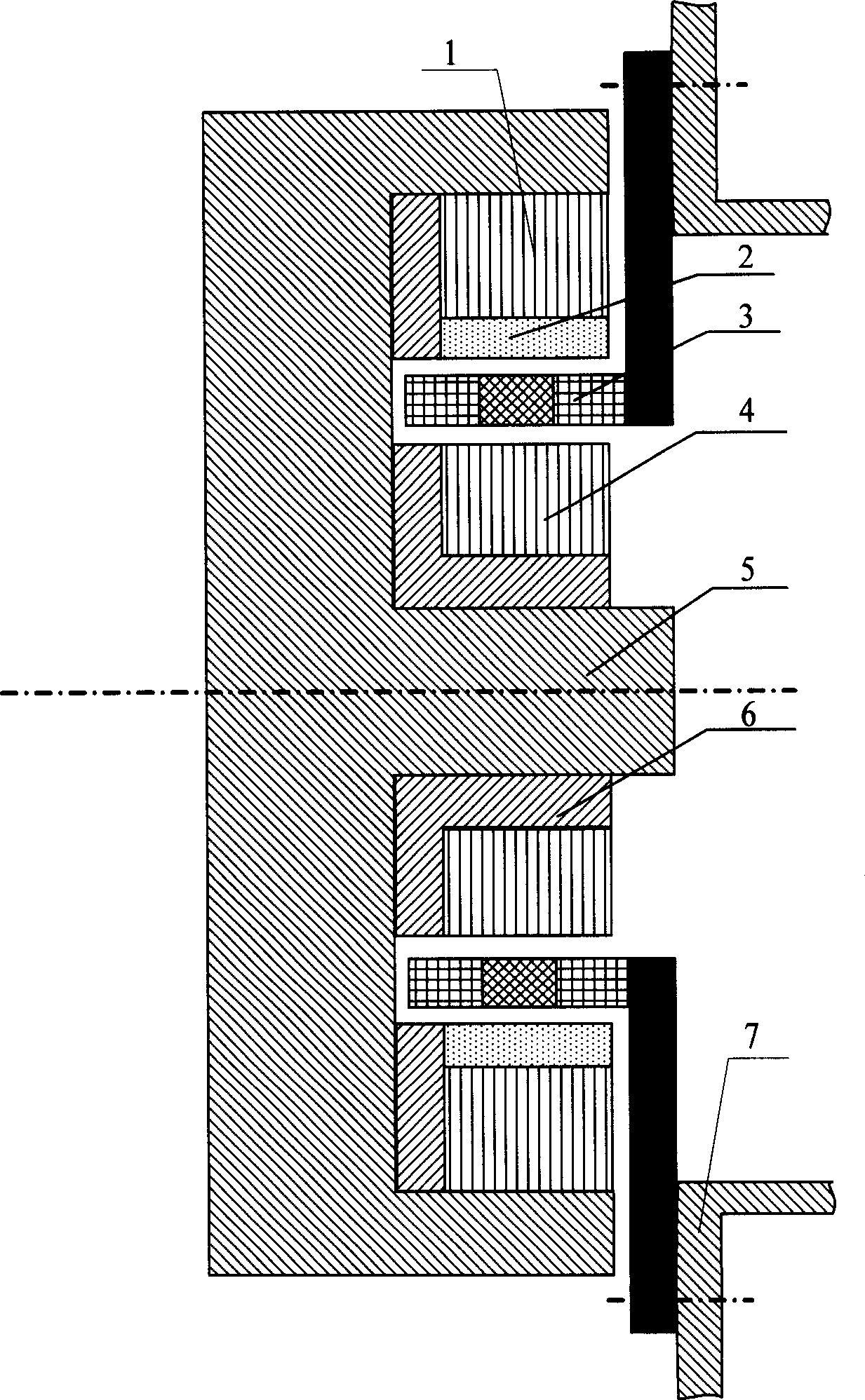
[0009] Such as figure 1 As shown, the present invention is composed of an outer rotor core 1, a permanent magnet 2, a hollow cup winding 3, an inner rotor core 4 and a rotor shaft 5, and both the outer rotor core 1 and the inner rotor core 4 are fixedly connected to the rotor shaft 5, so that the outer The rotor core 1 and the inner rotor core 4 rotate together with the rotor shaft 5. The permanent magnet 2 can be installed on the inner rotor core 4 or on the outer rotor core 1. Considering that the rotor will generate a huge centrifugal force when rotating at high speed, generally Place the permanent magnet 2 on the outer rotor core 1, the permanent magnet 2 is made of rare earth permanent magnet materials such as cobalt, ferrite, neodymium iron boron, etc., the magnetic flux generated by the permanent magnet 2 passes through the outer rotor core 1 and the inner rotor core 4 and The air gap between them forms a closed circuit, and the hollow cup winding 2 is fixed on the skel...


PUM


Abstract

The brush-less DC motor without stator iron core includes mainly outer rotor iron core, hollow cup stator, permanent magnet, inner rotor iron core and rotor shaft. Both the outer rotor iron core and the inner rotor iron core are connected to the rotor shaft for synchronous rotation; the permanent magnet is installed onto the outer rotor iron core or the inner rotor iron core; and the hollow cup stator is fixed to the casing. The permanent magnetic path is one closed loop comprising the outer rotor iron core, the inner rotor iron core and the air gap in between. Unlike traditional brush-less DC motor, the present invention has no stator iron core and rotor iron core divided into two parts including the outer rotor iron core and the inner rotor iron core, and has no stator iron loss radically and lowered total motor loss.

Description

Technical field [0001] The invention relates to a brushless direct-current motor, in particular to a brushless direct-current motor without a stator iron core, which belongs to the field of motors and can be used in occasions such as low power consumption and high speed. Background technique [0002] The body of the traditional brushless DC motor is the same as that of the permanent magnet synchronous motor. Due to the existence of the stator core, hysteresis and eddy current losses will be generated in the stator core when the motor is running. These losses are proportional to the 1.3 power of the rotor rotation frequency. Especially when the rotor rotates at high speed, it will generate huge loss in the stator core, which greatly increases the power consumption of the motor. At the same time, due to the existence of stator cogging, cogging torque and tooth harmonics will be generated when the rotor rotates, which will cause torque pulsation and cause certain losses. The n...

Claims


Application Information

Patent Timeline
Patent Type & Authority Applications(China)
IPC IPC(8): H02K29/00
Inventor 房建成孙津济马善振郦吉臣
Owner BEIHANG UNIV
Why Eureka
Try Eureka