
Near-field microscope of optical wave band

A microscope and near-field technology, used in scanning probe microscopy, scientific instruments, instruments, etc., can solve the problem of difficult spectral detection of optical signals, difficult to achieve signal-to-noise ratio, and difficult to achieve ultra-close distance control and scanning. Control and other issues to achieve the effect of increasing analytical capabilities

Inactive Publication Date: 2005-12-21
HUAZHONG UNIV OF SCI & TECH
View PDF0 Cites 11 Cited by
  • Summary
  • Abstract
  • Description
  • Claims
  • Application Information

AI Technical Summary

Problems solved by technology

This will make it difficult to achieve an appropriate signal-to-noise ratio in the operating band (optical band) without a photomultiplier tube
[0005] 2. Distance control and scanning control from the needle tip to the detected point of the sample. This mechanism can still overcome technical difficulties for flat samples, but it is almost difficult to achieve ultra-close distance control and scanning control for uneven samples.
[0007] 4. Due to the low light transmission efficiency of the probe, it is difficult for the optical signal collected by the probe to go through the spectroscopic system for spectral detection

Method used


Image

  • Near-field microscope of optical wave band
  • Near-field microscope of optical wave band
  • Near-field microscope of optical wave band

Examples


Embodiment Construction

[0034] The present invention will be described in detail below in conjunction with the accompanying drawings.

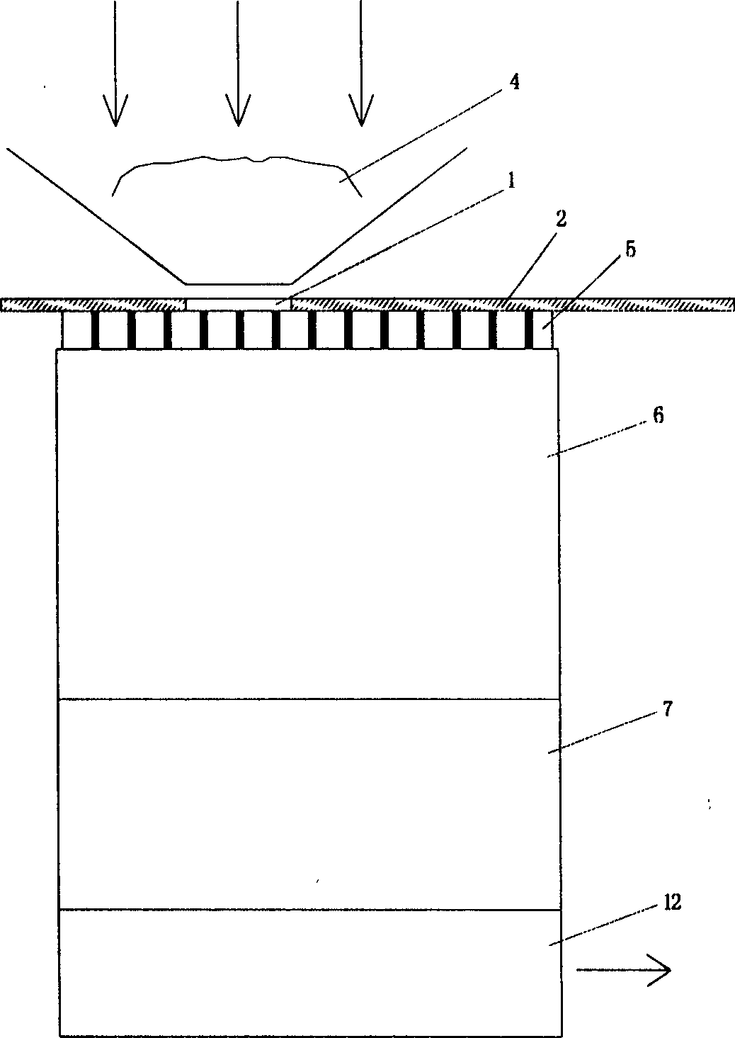
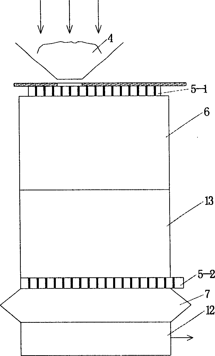
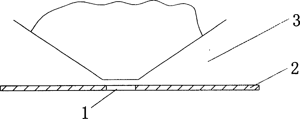
[0035] Figure 1 and Figure 3 show an embodiment of the present invention, the viewfinder 1 can be a rectangular light-transmitting window defined by a 7 × 9 or 9 × 7 array according to 63 steps as an example, and it is made on the side of the sample cell close to the sample On the wall 3; the opaque material film 2 covers the outer surface of the wall 3. And next to the viewfinder window 1 is the near-field encoding plate 5, the near-field encoding plate is made on the end face of a conversion optical waveguide 6, so that the light that comes through the viewfinder window is in those small holes in its limited area. In the converted optical waveguide, the near-field evanescent wave is gradually converted into a guided wave and sent to the subsequent device. The structure of the conversion optical waveguide 6 is a circular cylinder or truncated cone (or a square, pol...


PUM


Abstract

A near field microscope of optical band consists of near field viewfinder, near field coding plat , light wave guide for switching over , beam splitting system and photoelectric probe . It features setting near field coding plate as sub wavelength microhole array circulated as per S matrix distribution with microhole diameter being less than r value in Rayleigh criterion, picking up light coming from viewfinder and extracting it in microhole and converting it to be conduction wave for being sent to the following device.

Description

technical field [0001] The invention belongs to an optical band near-field detection device. Background technique [0002] Optical microscopes use uncharged photons as information carriers, which have little interference with cells and are a basic tool for biological / medical research. Although other types of microscopes, such as electron microscopes and scanning tunneling microscopes, already have sub-nanometer resolution, because the characteristic energy of electromagnetic waves in the optical band is similar to the molecular motion energy of biological substances, certain forms of interaction are prone to occur , so that these substances can be further understood through this interaction without damaging the biological activity of these substances. So many advanced laboratories in the world have been working hard to explore the characteristics of optical near-field so far, so as to use these characteristics to serve the development of human science and technology. One o...

Claims


Application Information

Patent Timeline
IPC IPC(8): G01Q60/18
Inventor 叶梅叶虎年
Owner HUAZHONG UNIV OF SCI & TECH
Learn More