

Particle analyzing chip with microflow control of single-cell algae
A microfluidic chip, particle size analysis technology, applied in the direction of individual particle analysis, particle and sedimentation analysis, analysis materials, etc., can solve the problems of high price, large volume, not suitable for on-site analysis, etc., to improve detection sensitivity and ensure stability. sexual effect
- Summary
- Abstract
- Description
- Claims
- Application Information
AI Technical Summary
Problems solved by technology
Method used
Image

Examples
Embodiment 1
[0023] Example 1: Structure of microfluidic chip
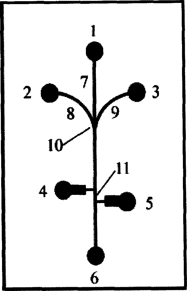
[0024] Such as figure 1 As shown, the structure of the microfluidic chip is divided into two parts: the liquid flow system and the detection system. The liquid flow system adopts a ψ-shaped structure, the middle channel is the sample channel 7, and the side branch channels are the sheath flow channels 8 and 9. The function of the sheath flow channel is to arrange the algae cells in the sample in a single row. 8 and 9 have the same size, the sheath flow channel is a 1 / 4 arc shape, and the tangential direction of the sheath flow channel 8 and 9 at the intersection point 10 is consistent with the direction of the sample channel 7, so that the sheath flow and the sample flow merge in the same direction, avoiding The eddy current disturbance generated by the convergence of the liquid flow ensures the stability of the liquid flow system; a double "T"-shaped detection channel 11 perpendicular to the sample channel ...
Embodiment 2
[0025] Example 2: Fabrication of microfluidic chip
[0026] 1. Fabrication of the glass substrate: Dimension design of the microchannel on the mask film: the fluid channel, 30 μm; the detection channel, 30 μm, 300 μm, with a width of 5 mm and a narrow length of 0.2 mm; the length of the common channel is 0.35 mm. Place the mask film on a 63mm x 63mm x 1.5mm uniform chromium plate, expose it to ultraviolet light for 180 seconds (wavelength 365nm), develop it in a developer for 100 seconds, and then dry it at 100°C for half an hour. The chromium film was etched with a chromium film etching solution (cerium sulfate: perchloric acid: water=50 g: 15 ml: 300 ml) at room temperature, then rinsed with high-purity water, and dried. The dimensions of the channels on the chromium plate measured by digital microscope photography are: sample channel, 40 μm; detection channel, 40 μm, 310 μm. With 0.5M HF / 0.5M NH 4 F etchant etches the bare borosilicate glass at a rate of...
Embodiment 3
[0029] Example 3: Microfluidic chip analysis and detection system
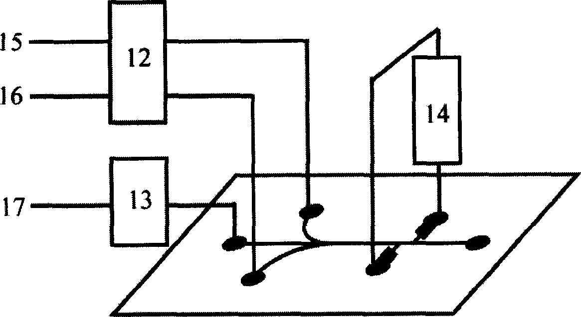
[0030] Such as figure 2 As shown, the inlet 1 of the sample channel 7 is connected to the sample pump 13, the sheath flow channels 8 and 9 on both sides are connected to the sheath flows 15, 16 at their inlets 2 and 3, electrodes are arranged at the two ends 4, 5 of the detection channel 11 and It is connected to a constant current meter to form the whole microfluidic chip analysis and detection system. The sample and the sheath fluid are transported by the pumps 12 and 13, the sheath fluid flows at the same flow rate, and the sheath fluid flows forward in the form of laminar flow after converging with the sample. By adjusting the sheath flow and sample flow rate, the cells in the sample are Arranged in a single row and move forward through the detection area (the common area of the detection channel and the sample channel), the cells in the detection area replace the equal volume of electrol...
PUM
 Abstract
Description
Claims
Application Information