Fuel jet valve for internal combustion engine

A fuel injection and internal combustion engine technology, applied in fuel injection devices, mechanical equipment, engine components, etc., can solve problems such as the limitation of degrees of freedom, and achieve the effects of elimination of limitations, stable operation, and suppression of pressure fluctuations

Inactive Publication Date: 2006-01-04
DENSO CORP
View PDF1 Cites 5 Cited by
  • Summary
  • Abstract
  • Description
  • Claims
  • Application Information

AI Technical Summary

Problems solved by technology

But this will limit the freedom of design

Method used


Image

  • Fuel jet valve for internal combustion engine
  • Fuel jet valve for internal combustion engine
  • Fuel jet valve for internal combustion engine

Examples


Embodiment Construction

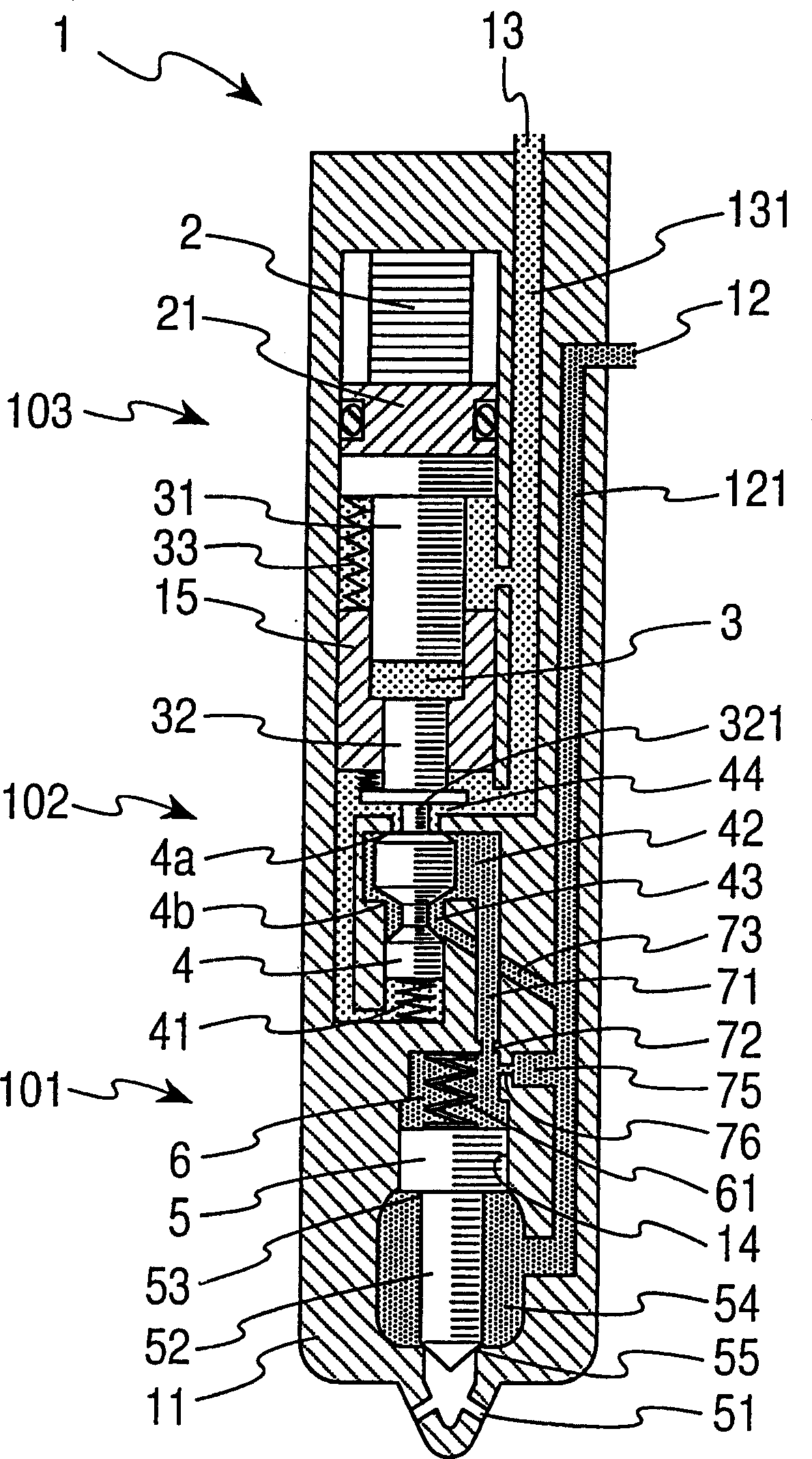
[0014] see figure 1 , which shows a fuel injection valve 1 according to an exemplary embodiment of the invention. The fuel injection valve 1 of this embodiment is used in a common rail fuel injection system of a diesel engine. A plurality of fuel injection valves 1 are placed according to corresponding cylinders of the diesel engine, and receive fuel from a common rail common to the plurality of fuel injection valves. The high-pressure fuel supply pump supplies the fuel from the fuel tank to the common rail, and the common rail converges the fuel to a predetermined high pressure (for example, 20 to 200 Pa) consistent with the fuel injection pressure.

[0015] The lower end portion of the fuel injection valve 1 has a nozzle portion 101 including a nozzle needle 5 . The fuel injection valve 1 is installed such that the nozzle portion 101 protrudes into a combustion chamber. The fuel injection valve 1 has a hydraulic control unit 102 (hydraulic control valve) in the middle. T...


PUM


Abstract

The present invention discloses a kind of fuel oil jetting valve, which regulate the oil pressure cavity pressure acting on the nozzle needle valve for opening and closing the jetting hole in the valve closing direction. By means of the piezoelectric brake driving the valve in the oil pressure controlling part, the fuel oil jetting valve makes the pressure in the oil pressure regulating cavity increase or decrease. The oil pressure regulating cavity is communicated with the oil pressure regulating part via the main channel and the high pressure channel via the subsidiary channel. The main channel and the subsidiary channel forms main throttle hole and subsidiary hole separately near the opened end of the oil pressure regulating cavity, and the main throttle hole and subsidiary hole have positions so selected that the pressure fluctuation inside the oil pressure regulating cavity is suppressed.

Description

technical field [0001] The invention relates to a fuel injection valve structure for a common rail fuel injection system of an internal combustion engine. In particular, the present invention relates to a structure of a back pressure medium passage that suppresses back pressure fluctuations of a nozzle needle. Background technique [0002] The common rail fuel injection system of the diesel engine gathers the fuel in the common rail and provides it to the fuel supply channel of the fuel injection valve. The common rail type fuel injection system injects fuel by opening and closing an injection hole formed at the tip of each fuel injection valve with a nozzle needle. A regulating oil pressure chamber is formed at the rear of the nozzle needle. Regulating the pressure in the oil pressure chamber is controlled by the oil pressure control valve. The nozzle needle is raised or lowered by driving the hydraulic control valve by a driving unit using a piezoelectric actuator. In ...

Claims


Application Information

Patent Timeline
Patent Type & Authority Applications(China)
IPC IPC(8): F02M61/10F02M47/02
Inventor 堀内康弘猪头敏彦
Owner DENSO CORP
Why Eureka
Try Eureka